Linkages, joints and frames; the basics of Kinematic synthesis (MFKNMAT & LBYMF3A)
TARGET AUDIENCE: Students, Academics, Industry Professionals, Employers, and Tech Enthusiasts
About the Thumbnail: A simple grashof 4-bar crank-rocker linkage with a quick return. Seen in many mech designs! Note: Casual taglish; No deep takes but cover enough to keep the discussion flowing.
OVERVIEW: Kinematics is the study of motion without the regard to forces. The sweet spot where the system functions as intended is called a mechanism synthesis where in your kinematic chain and components (linkages, joints and frames) work to acheive the desired output.
I present here my undergraduate studies that focused on this topic. Its basically a dump of all of the mechanisms that we study so that we know how to design our own machineries in the future. By the end, i’ll let you know my take on the usefulness of this and when can we use this in the field.
Before that, let me present an overview of the topic and the basics we covered!
Grashof’s Law and Four-Bar Linkages
The simplest planar mechanism is the four-bar linkage. It consists of four links connected in a closed loop by four revolute joints.
The Grashof condition predicts the relative mobility of the links based on their lengths.
If we let:
- (s) = length of the shortest link
- (l) = length of the longest link
- (p, q) = lengths of the other two links
Then Grashof’s Law states:
\[s + l \leq p + q\]Cases:
- Grashof (s + l ≤ p + q): At least one link can rotate fully.
- Non-Grashof (s + l > p + q): No link can make a complete revolution; only oscillatory motion.
Four-bar link varieties:
- Double-crank: both adjacent links to shortest link rotate fully.
- Crank-rocker: shortest link adjacent to fixed link → crank rotates, opposite link rocks.
- Double-rocker: shortest link is opposite the fixed link → both rock.
- Slider-crank: a limiting case when one link becomes infinitely long (a slider).
All these mechanisms, we tried to model via F360 and I will provide with the samples that I have made in the next section. I want first to establish first here the slider-crank mechanism which drives many actuators.
Slider-Crank Mechanism
A slider-crank is essentially a four-bar linkage with one infinite link. It converts rotary motion into linear motion.
- Applications: internal combustion engines, compressors.
-
Kinematic relations:
\[x = r\cos\theta + \sqrt{l^2 - (r\sin\theta)^2}\]
If crank has angle (\theta) and length (r), and connecting rod length (l), slider displacement (x) is:
This nonlinear relation explains piston motion.
Another things that I find interesting is coupler curves and its corresponding motion. This accompanies the 4-bar mechanism traces.
The coupler link (floating link) of a four-bar mechanism traces complex paths.
- The locus of a point on the coupler is called the coupler curve.
- Coupler curves can generate approximate straight lines (e.g., Watt’s or Chebyshev’s linkages).
This property is exploited in path generation problems where you want the coupler point to pass through given target positions.
Motion Generation Synthesis
Now, of course to generate the position of these linakges, we want the desired output positions of these linkages to achieve the wanted orientation and path. The fundamental of these are the 2-position synthesis and 3-position synthesis.
2-Position Synthesis
For two desired output positions (e.g., rocker angle or coupler orientation), we solve geometric equations to ensure the linkage passes through both.
- Rocker output: specify two angular positions of rocker.
- Coupler output: specify two positions of a coupler point.
- Solution: construct circle/line intersections to satisfy constraints.
3-Position Synthesis
Three prescribed positions provide stronger motion control.
- The essence: pick 2 or 3 points in space as desired outputs for the coupler or rocker.
- The mechanism is synthesized so that the actual motion interpolates these points.
- For planar four-bars, three positions are the maximum that can be exactly matched (beyond that → approximate synthesis).
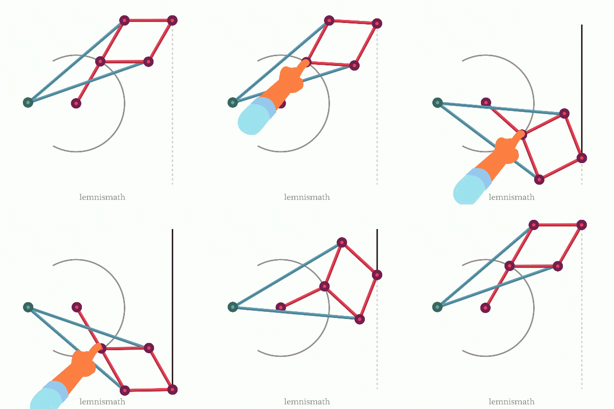
There are many other synthesis that must be considered if the designer will want to product the desired motion regardless of applied forces. An example of this would be the straight-line linkages seen below like chebs and peau-lipkin (I find this very cool as the conversion of rotary motion to a straight motion has many application!)


Now let me cover the stuff that I was able to model and study to determine its motion~~
Backhoe Excavator Motion
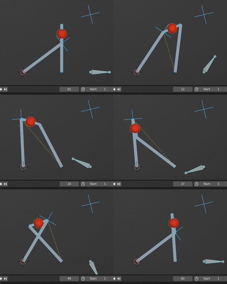
Based on the given picture I provided here how a backhoe move which is a 2-part articulating arm.

Graphical Linkage Synthesis (Slider-Crank)
With the given ternary link and set grounds and linkage length and angle, I was able to make this crank-slider mechanism.

Prismatic and Revolute Joints; Defining this in software

CAM Follower
A cam follower sample where the movement is dependent on the body inside the follower, intended movement mimics a simulated toy motion. (diko lang maipikita ung laruan :<)

Gear Box
Another common validation that is done for kinematic motions is the performance of gears in set degrees of shaft. I show here a gearbox and a samll output indicator to check if the output is as intended.

Pick and Place Model
Lastly, the most complicated model that I did to study its movement is this pick and place end effector. There was not straight path for this; Despite the reference avaialble in YT here the implementation they did was the final product in Solidworks. I had to reverse engineer this and implement it in F360.
This is the culmination of the activities as this covers the complex mechanisms discussed from rocker to a specific movement for motion study.

REFLECTIONS:
Of course, the beauty of kinematic mechanisms is that the machine is able to make our life easier by moving as desired. This comes in my fields like Robotics: where link synthesis should be considered manipulators. In fact, denavit-hartenberg names is felt in this field with their contribution of the term cognates which is the fancy term for the position synthesis for any n-link. We did determine that 4-bar linkages is the optimal use of linkages and considering beyond this goes into theortical territory.
Aside from this, I think I did mention that actuators should abide to these overall principles like Engines & Pumps: that will do slider-crank mechanism for power transmission. I’ve seen physical Packaging machines: that utilizes cam and coupler mechanisms for intermittent motion (geneva mechanism too~!)
Personally, all this is self-taught and engrained into memory. Nagiging pababaya ung instructor samin and I do believe that if you really want to apply this in real projects, it will be most likely in product development and research and development for specific product designs. Other than this, its more of the intuition of the movement of the product to practically define it is a way to use this in the field!
Lmk in the comments your other takes for this ( ๑‾̀◡‾́)✨
Enjoy Reading This Article?
Here are some more articles you might like to read next: