CNC Machining and various advanced manufacturing techniques (LBYMF3H)
TARGET AUDIENCE: Students, Academics, Industry Professionals, Employers, and Tech Enthusiasts, Self
About Thumbnail: Its a photo of me handling and programming the CNC machine to create our 6-sided dice!! :>
OVERVIEW: As someone who is very excited with large machineries and how they work, finally I was able to utilize and try the CNC machine seen in one of our labs in uni. It was such a cool experience that has become a core memory in my stay in MEM department! I know it sounds dumb but that child-like ethusiasm to see how a workpiece is being made after a well-planned execution (via G-code) is a very comforting feeling in this line of work. Aside from that, other known advancements in manufacturing was also explored in the course. Notably, I have here below my findings and effort for CNC machining, laser engraving and 3D printing :))
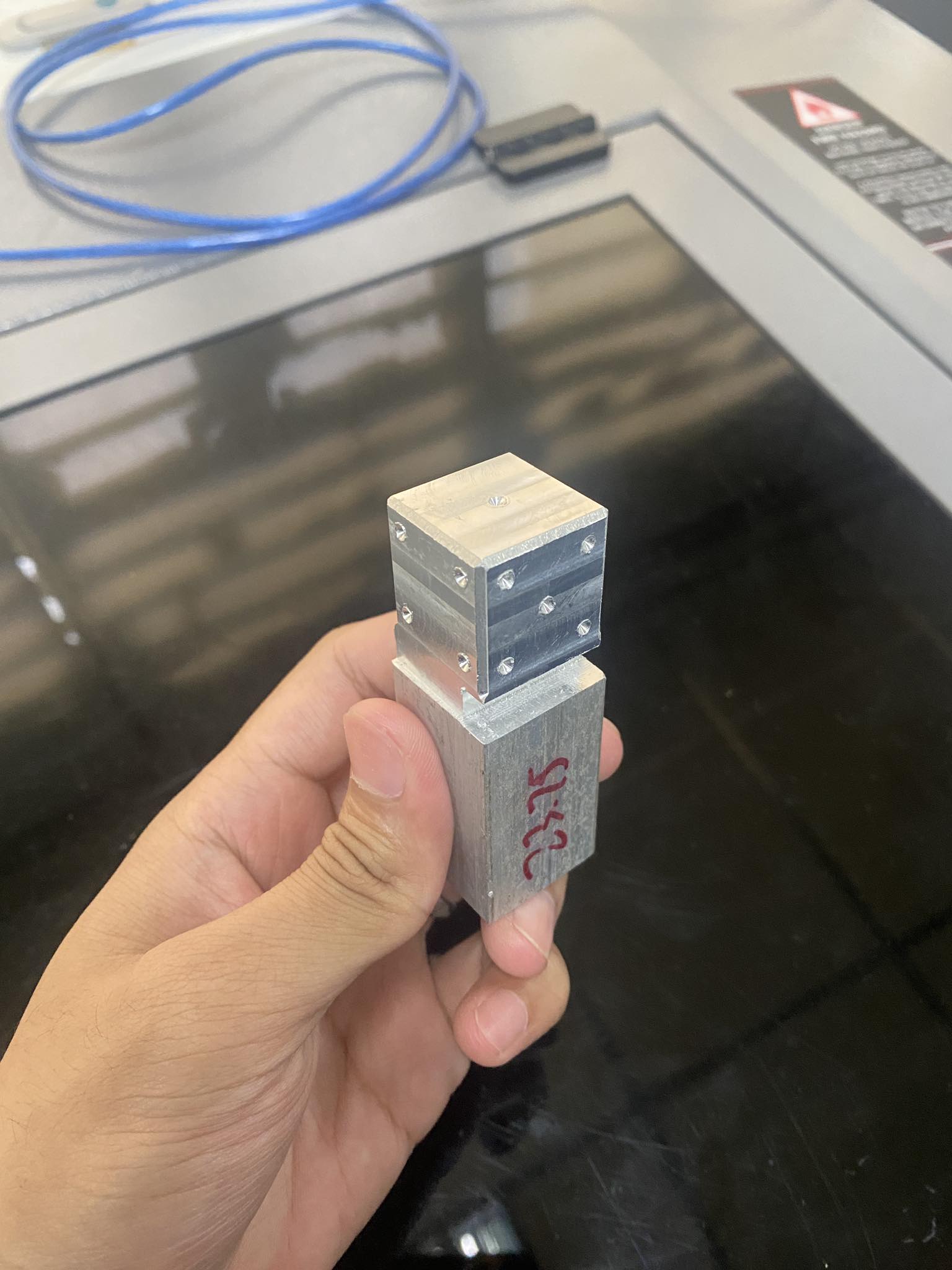
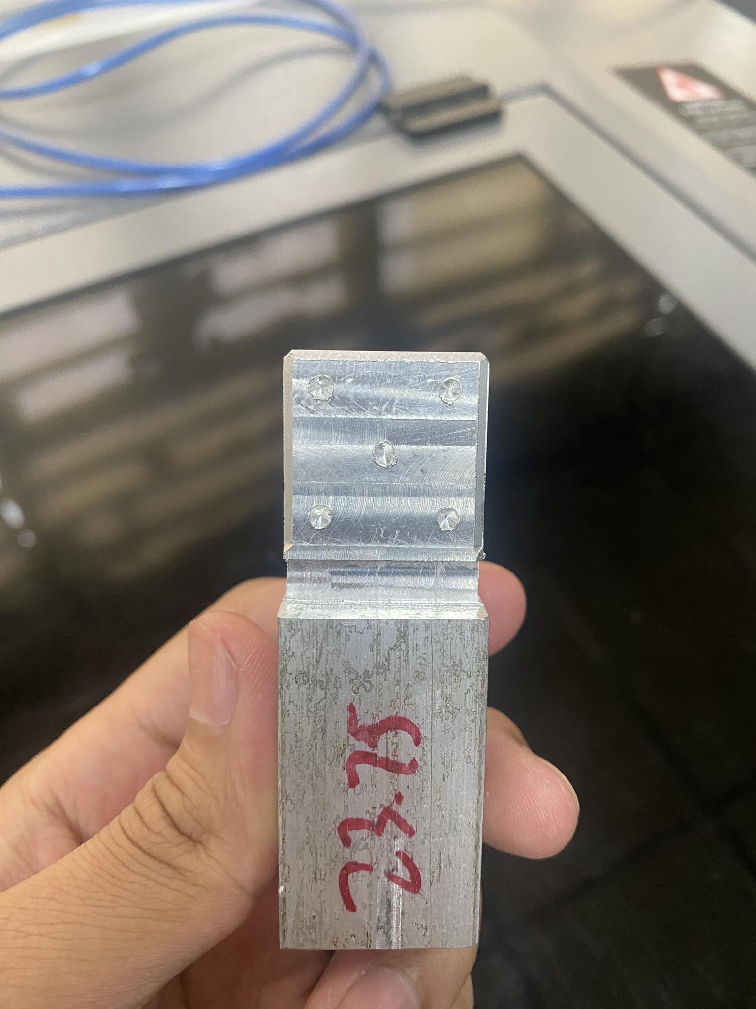
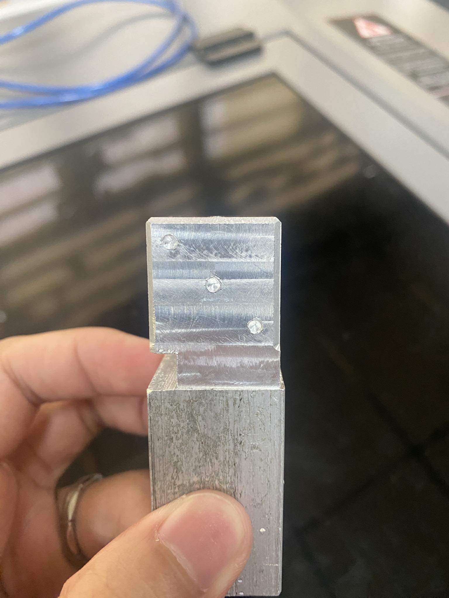
CNC-Machining for a 6-sided dice:
The activity detail the process of CNC milling programming and operation for creating a 5-axis dice using Fusion 360 and a Haas VF2 machine, covering both design and manufacturing aspects. I was able to emphasize the importance of understanding machine setup, tool and work offsets, and G-code programming for successful 5-axis machining.
The design and manufacturing process within Fusion 360, emphasize my ability to define user parameters to define stock size and the creation of setups for facing, drilling, chamfering, and contouring operations. This was a parametric model so tweaking the values in set variables were already given, I just have to exact in to wanted setup in the mill machine. A key challenge that I encountered was with circular patterns, requiring manual adjustments to the processes in the fixture.
I detail also the practical operation of the CNC milling machine, specifically the Haas VF2 with TRT160 , to create the dice. It emphasizes the importance of understanding how to set up for 5-axis machining and its pros and cons. The procedure involves loading tools, setting work offsets (G54), and using tools like an edge finder and dial indicator for precise measurements.
I explicitly mentioned that the 5 Axis Operation, the G54 Work Coordinate Origin is always placed at the point where the A axis and B axis meets in the mill bed. I was able to compensate for offsets in the CAM software due to the machine’s lack of TCPC (Tool Center Point Control) and DWO (Dynamic Work Offsets). The process includes facing, drilling, chamfering, and grooving operations, with careful attention to tool height offsets and wear compensation.
You may see the iterations, process and final product further below!
Laser Engraving
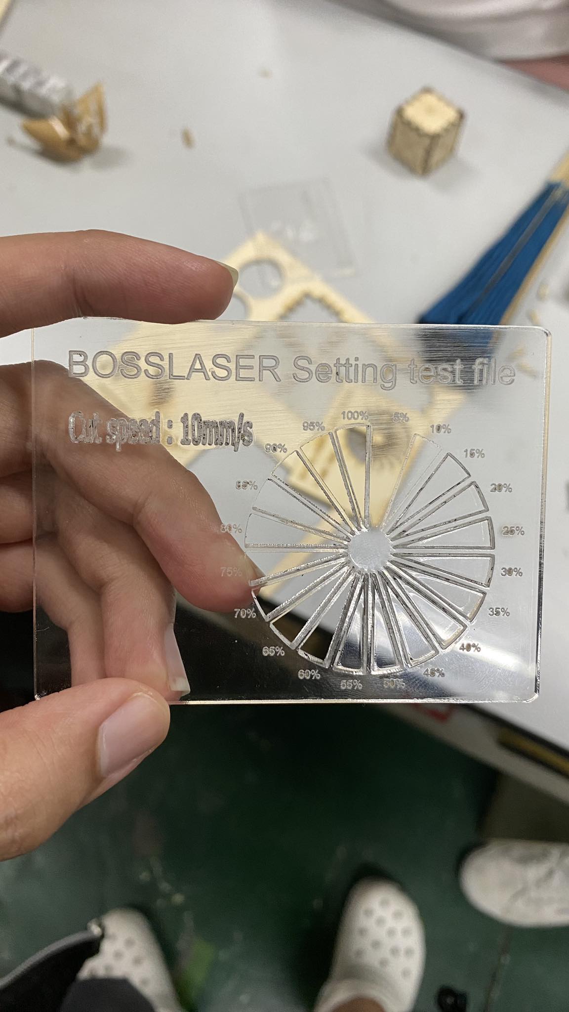
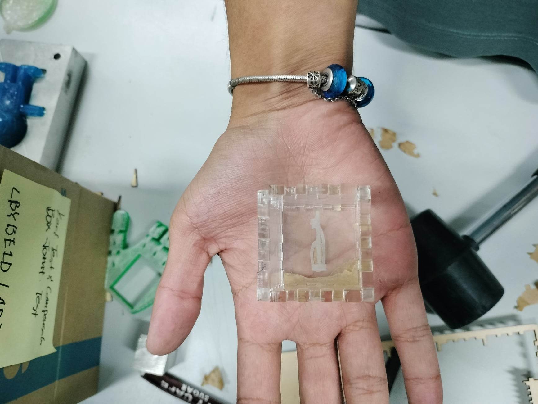
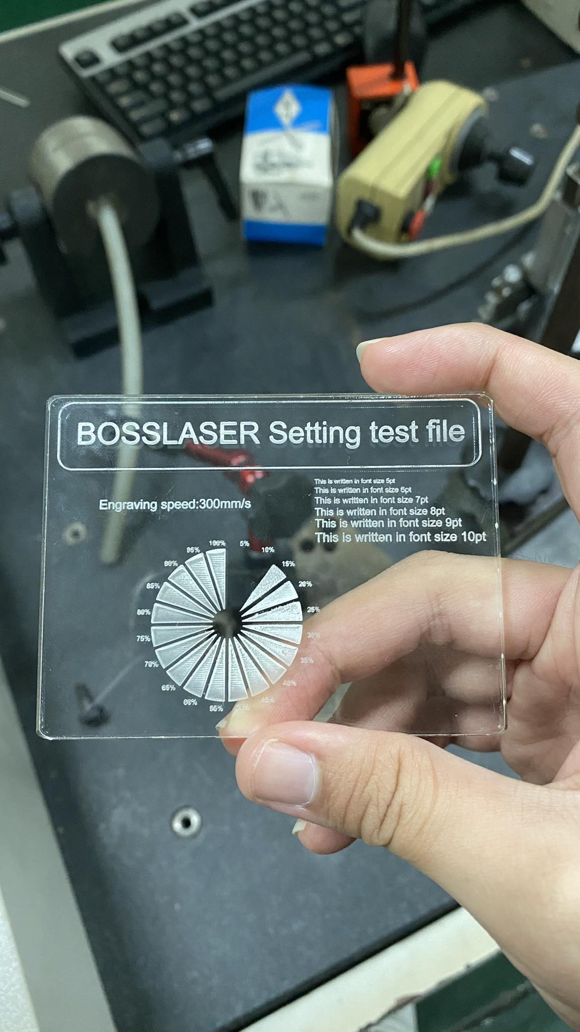
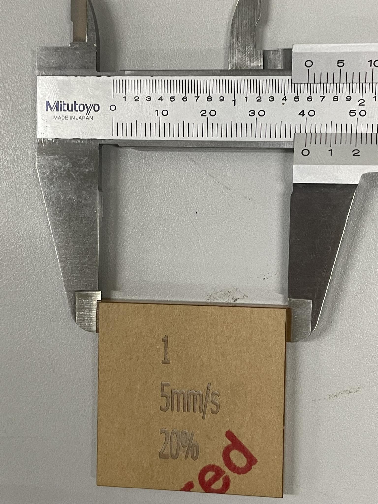
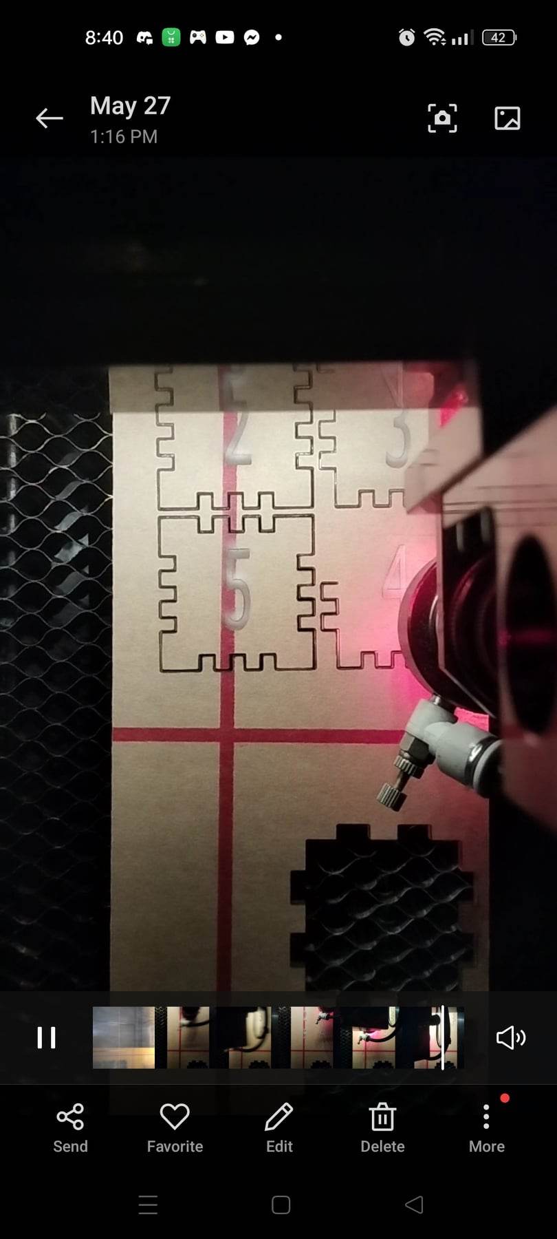
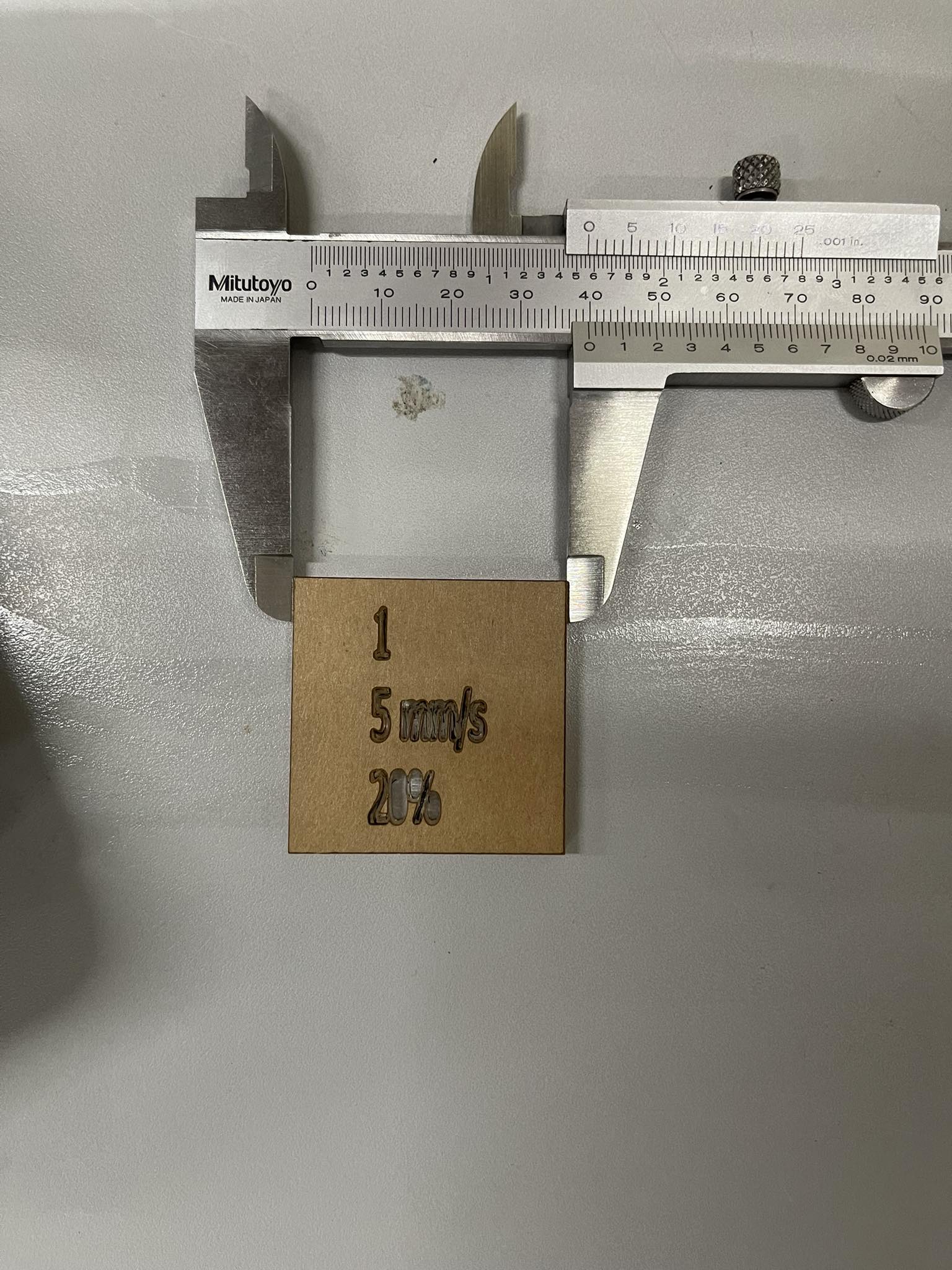
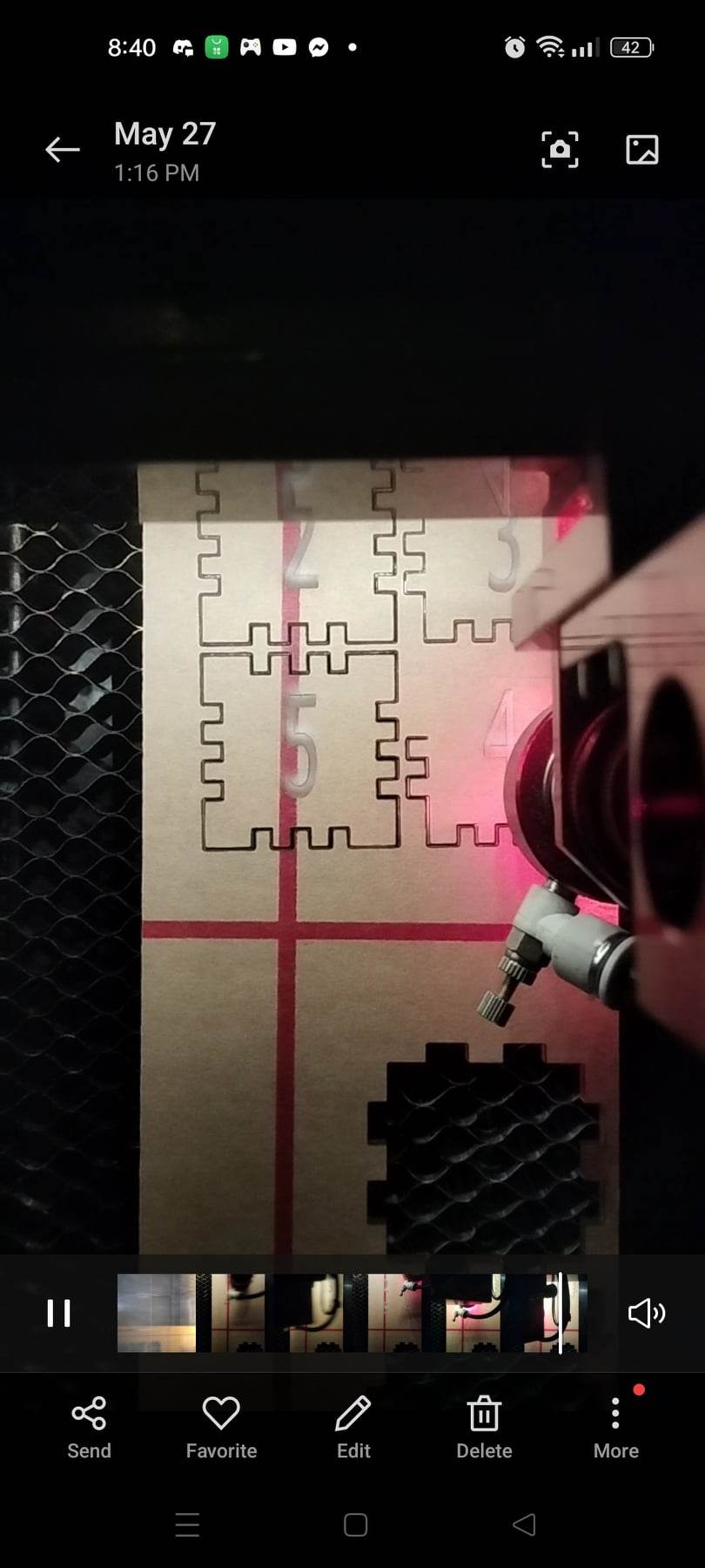
For this activity, I was able to perform laser cutting and engraving techniques, focusing on calibration, kerf compensation, and box design. First, the calibration involves the know-how of the laser power and testing parameters for new materials. Bosslaser software was used for setting up the test cuts and needed setting to perform the engraving operations in chosen material, to be acrylic. I adjusted laser power and speed to find optimal settings, ultimately determining the laser power of cutting the acrylic material to be specifically 85% at 5mm/sec speed with the cut test information. Laser power for acrylic for the engraving operation is determined to be 20% power at 300 m/s speed.”
After this, I perfrom kerf compensation which is a known phenomention where laser cuts through material it burns away a small amount that needs to be factored in the cut to compensate on the operation. I cut a 40mm square, measure the cut piece and the hole, and compute the laser offset that is then counteracted with a scaling of the design. Finally, I made the simple box design where in an interference fit was provided. This required the previous activities to be done to generate a box design by given design parameters wanted by user and embellishments. With this, I was able to give out fits—clearance, transition, and interference utilizing an online tool festi to generate box designs and test different fits, ultimately leading to the assembly of a laser-cut box. The exercises collectively provide a practical understanding of laser cutting principles and techniques.
Simple FEA of a Phone-Stand
Lastly, I provided a simple improvement for a phone-stand that enables it to be foldable in this activity. Seen below, is a standard acryclic phone stand that is not ideal for placing it in one’s bag. The feature of making it foldable enables it to be travel-friendly and compact for storage. I was able to make the following modifications.
Key Modifications:
- Added a base stand with rubber matting for support.
- Implemented joint connections from base-to-arm and arm-to-frame for weight transfer.
- Included joint connections on phone hold contact points for folding functionality.
- Added fillets to all contact sets for smoother edges and easier 3D printing.
With these changes in place, I further validated the design with a simple finite-element analysis (FEA) done in F360. Here are my findings:
- FEA was performed to determine the design’s strength under a load of
27.5N (5.5 N with a safety factor of 5). Which is roughly 3kg of rigidity while maintaining its functionality. - Challenges were encountered in defining constraints for the FEA due to the added joints.
- Acrylic clear was used as the primary material, with rubber matting for the base.
The printing simulation estimated it to take atleast 4 hours to print with support but that may change with the infill pattern and consideration for the folding joints that I have made.
REFLECTIONS: This lab class has so much potential but I never got to fully utilize it in my stay in college. It was a bummer but I think if I just prodded more to utilize the CNC machine to fabricate my own sets of cool project ideas, I would have been able to take advantange of it more. Of course, tasting it left me wanting more espeially CNC machines are hard to come by. Of course, different vendor of the machine should also be taken accounted for; Haas is standard but other specialized machines are often has a problem with interconnctivity of its product to other planning/execution software called “vendor lock-in”. F360 and I believe Solidworks provide a workaround and constant support of keeping updated its library to suit given machine.
Overall this experience held a sentiment in the back of my mind that the next time that I get to try a CNC machine, I will definitely prepare one project for me to manufacture!!
Enjoy Reading This Article?
Here are some more articles you might like to read next: