Exploring Power Electronics through simulations
TARGET AUDIENCE: Students, Academics, Industry Professionals, Employers, and Tech Enthusiasts, Self
Note:
OVERVIEW: One of the many things that is often overlooked in an electronic application is the power control and conversion of electricity with high efficiency inside the device. It seems so simple and ubiquitous that you don’t really notice it until an issue arises. Either this can be in a form of battery cell leakage and improper distribution or simple electromagnetic interference that causes the product peripherals to malfunction.
This blog post covers my exploration to power electronics and its use case. Power electronic converters can be divided into four groups: AC-DC converters (rectifiers), DC-AC converters (inverters), DC-DC converters, and AC-AC converters.
I’ll be using MATLAB and Simulink heavily to properly convey the inner workings of power electronics. These are tools for computer simulation to virtually investigate the behavior of the system under study. Computer simulation for power electronic converters is an easy, safe, and cheap way to observe the behavior of the converter (i.e., voltage of nodes and current of branches) and ensure that the converter does what we exactly need.
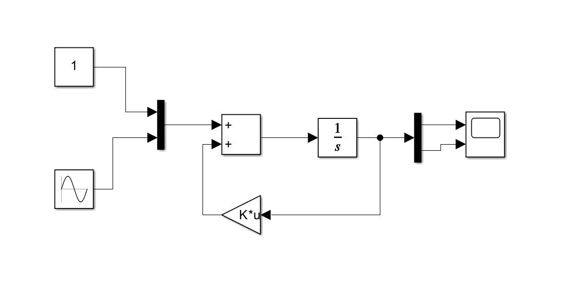
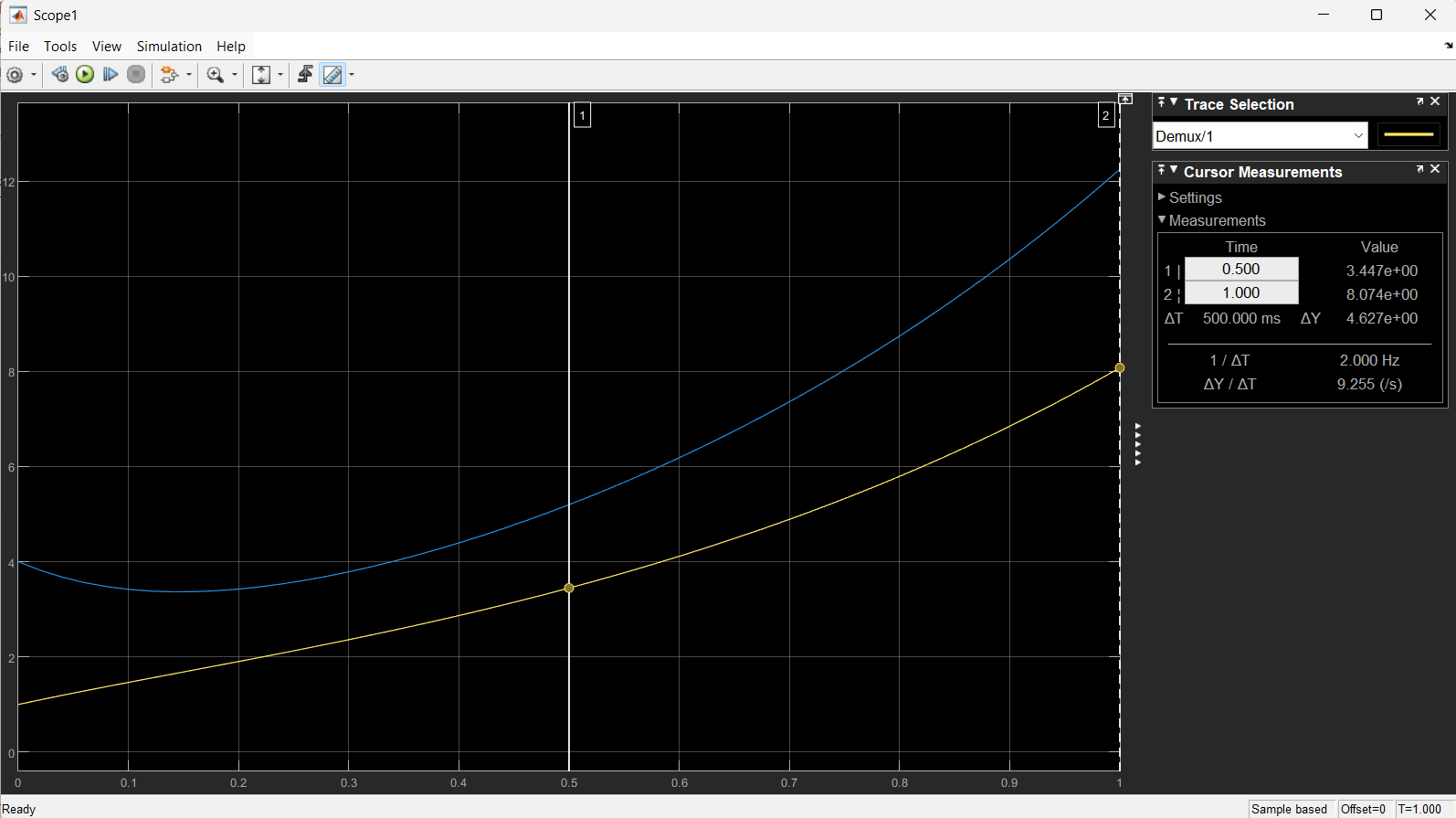
Lets start with the basics. Power electronics can be defined in differential equations that define the behavior of the over a period of time. These are time-domain differential equations. While they tell us a lot, they can become complex to solve directly—especially when systems have multiple inputs and outputs. That’s where the state-space representation comes in. It transforms time-domain equations into a more structured, matrix-based form that is easier to analyze, simulate, and implement in tools like MATLAB/Simulink. As an example for this, below is a simulink model that I did that represents a differential equation (dynamic systems) with only one integrator block.
Simulation of a Dynamic System with Only One Integrator Block
A dyanamic ssystem is given in the form of a second-order differential equation:
\[\dot{x}_1 = x_2, \quad \dot{x}_2 = 10x_1 - 5x_2 + 7\sin\left(3t + \frac{\pi}{3}\right), \quad x_0 = [14]\]where: This describes the dynamics of the system:
- (x_1) could represent a position, voltage, or current.
- (x_2) is the derivative of (x_1), often velocity or rate of change.
- The sinusoidal term is an external input (forcing function).
State-Space will tell us that the equation above can be simplified through its state vector:
\[x = \begin{bmatrix} x_1 \\ x_2 \end{bmatrix}\]The system can then be rewritten in state-space form:
\[\dot{x} = Ax + Bu, \quad y = Cx + Du\]In the example:
-
System Matrix (A): \(A = \begin{bmatrix} 0 & 1 \\ 10 & -5 \end{bmatrix}\)
-
Input Vector (u): \(u = \begin{bmatrix} 0 \\ 7\sin\left(3t + \frac{\pi}{3}\right) \end{bmatrix}\)
Control can therefore be applied more easily knowing the transform equation above. Particularly control design in the form of PID tuning, state feedback are excellent to govern such systems. To refer back to power, this equation is closely related to buck converter where in (i_L) (inductor current) and (v_C) (capacitor voltage) are chosen as states. Writing them in state-space allows you to easily simulate how the output voltage responds to switching or load changes.
Simulation of the Dyanmic Equation of a Boost COnverter
In this section, I now go over the simulation of the dynamic equation of a boost converter and its equivalent circuit using a MOSFET. The state variables are defined as follows:
We define the state variables as:
- (i_L(t)): Inductor current
- (v_C(t)): Capacitor (output) voltage
Input: (V_{in})
Load: Resistor (R)
Control input: Duty ratio (D \in [0,1])
Components are assumed ideal (lossless MOSFET, diode, inductor, and capacitor).
Averaging over one switching period with duty cycle (D(t)), we get the following equation that considers an open MOSFET:
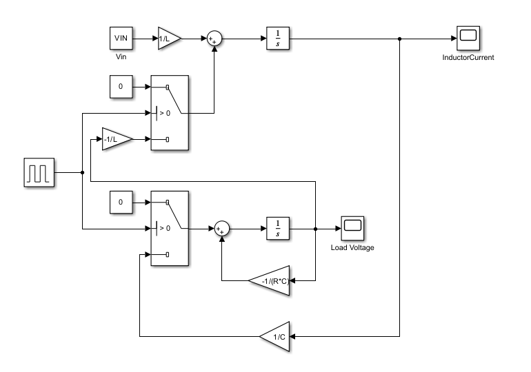
\[\dot{i}_L(t) = \frac{V_{in} - (1-D(t))\,v_C(t)}{L}\] \[\dot{v}_C(t) = \frac{(1-D(t))\,i_L(t)}{C} - \frac{v_C(t)}{R C}\]Below are the schematics for the circuit.
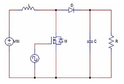


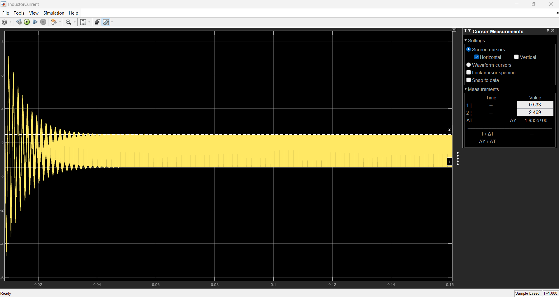
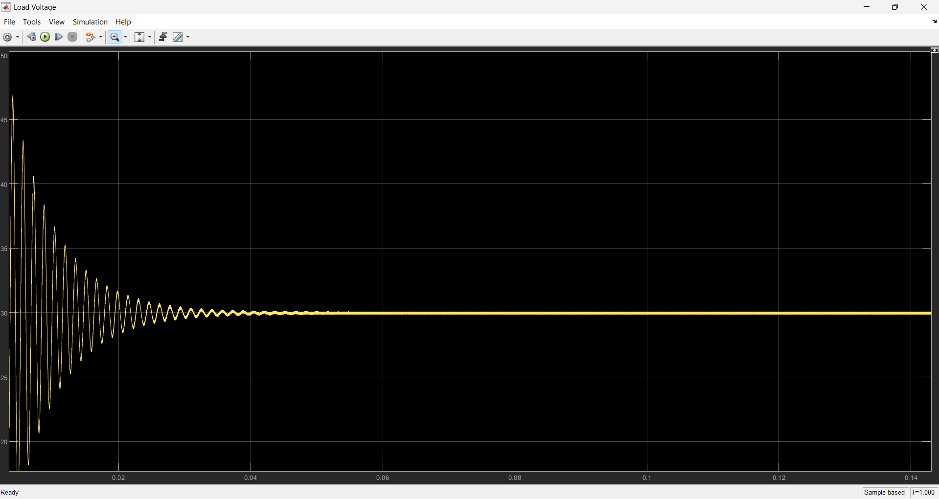
Below features the simulink model that I have made that defines the different blocks and values to simulate the boost converter. In the MATLAB workspace, I have defined initial conditions for the input voltage (VIN) to be VIN=12 volts, load resistance (R) to be R=50 ohms, load inductance (L) to be L=150e-6 or 150 micro-henries, output capacitance (C) to be C=76e-6 or 76 micro-farads;
A pulse generator is utilized as input for the MOSFETS to simulate a 25kHz frequency (f) with a duty cycle when switch on to be DutyCycle=0.6.
Running the simulation, we are able to see the boost conversion of the initial 12V is successful with a translation of voltage into 30V with a maximum current given to be 2.46 A. Another cool insight about this is how quickly the system is able to plateau in given values as time domain is set to be only 1 second. This shows that the system is reliable to quickly provide the needed voltage-current to peripherals but caution should be noted of any in-rush current and voltage at the start that some components are sensitive to. Like the voltage output has its peak voltage reach 60V which is more that double the expected output of 30V.
Again, this type of setup is also dependable on the initial conditions of the system and values of the passive components. Should the values change, the expected output voltage and current will also change. Determining the right values of the components is a different challenge that may be covered in another section.
Simulation of a 3-Phase Diode Rectifier (Uncontrolled)
This section now covers AC-DC converters, more commonly known as Rectifiers. They are commonly seen to drive DC motors and charge battery cells with known power coming from wall outlets. There 2 types of rectifiers, one of which is a diode rectifier that is known to be uncontrolled. This is because the output of these rectifiers cannot be changed by the user and is of constant value. I cover here the more sophisticated 3-phase diode rectifier or bridge rectifier that I did in my analog class along with a transformer! Now I will dive deeper seek how to simulate this via the simscape library where I aim to get the average and RMS values~~
REFLECTIONS:
Power electronics is a very broad subject and with my job as a mechatronics engineer, this is very important for enabling efficient control and conversion of electrical energy to drive actuators, sensors and embedded devices. I can definitely see this application for future works like that of robotics, in the manufacturing plant and industrial automation.
Despite it being a device that is often disregarded, the complexity that is needed for their design is subject to the realities of engineers who deal with this type of systems from nonlinear switching devices, passive components and control strategies.
Overall, prototyping and analysis such dynamic behavior is tedious and time-consuming. That is why utilizing MATLAB and simulink transforms this type of validation workflow into a more easy and straight-forward action. I was able to visualize dyanmic response, validate design assumptions, ensure safety and iterate without using physical units using the enivronment and which I have demonstrated here!!
Let me know if there is anything I missed that is worth studying for power electronics!
Enjoy Reading This Article?
Here are some more articles you might like to read next: