Modified Field Sobriety Test
A device to standardize field sobriety testing against DUI and DWI in line with R.A. 10586 as an alternative to the conventional breathalyzer 🍻
OVERVIEW:
The motivation for this project is the increasing road fatality cases caused by driving while intoxicated (DWI) and driving under the influence (DUI) here in the Philippines. This project proposes a cheaper alternative to the common breathalyzer used by police to test intoxication. This Modified Field Sobriety Test device using an Arduino Uno. The system integrates sensors, actuators, and displays to help law enforcement evaluate a driver’s sobriety in an automated way. The project simulated three standardized tests—balance, cognitive ability, and walk-and-turn—replicating real-world applications of embedded systems in public safety. Both simulation and a ready PCB was made for this project.
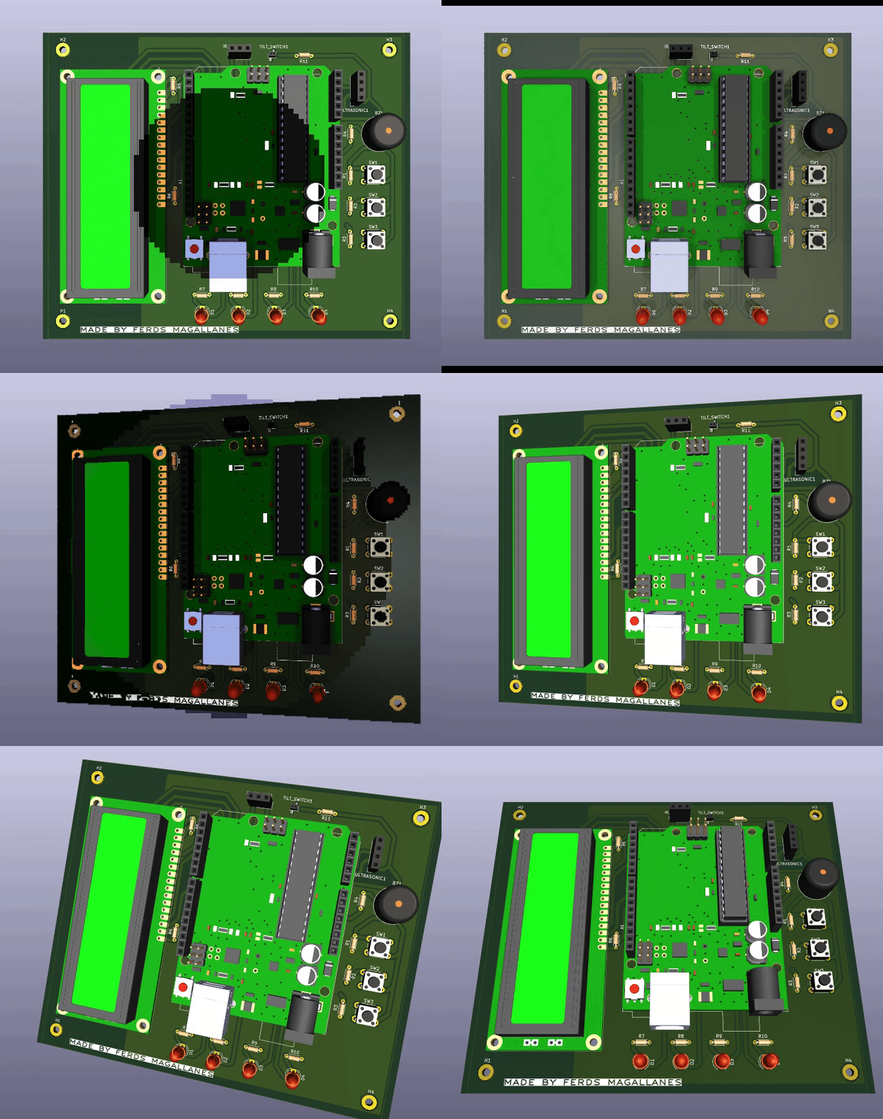
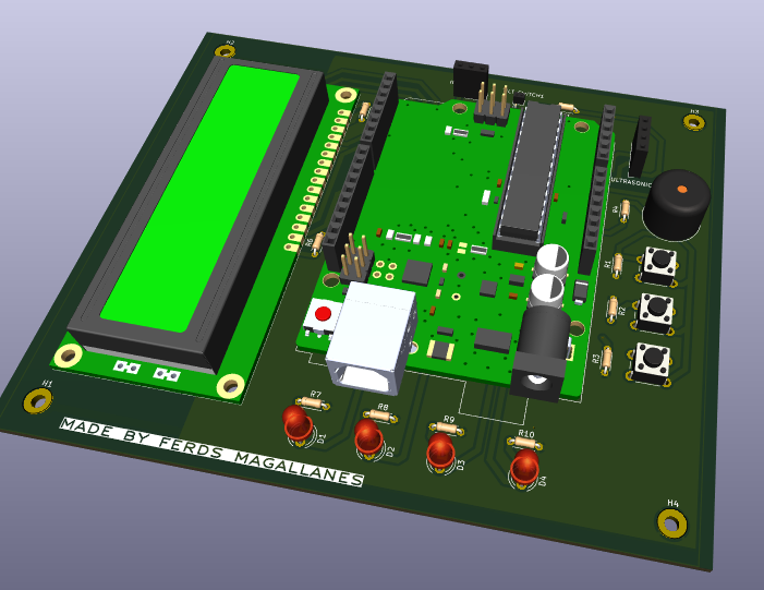
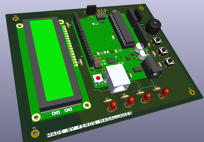
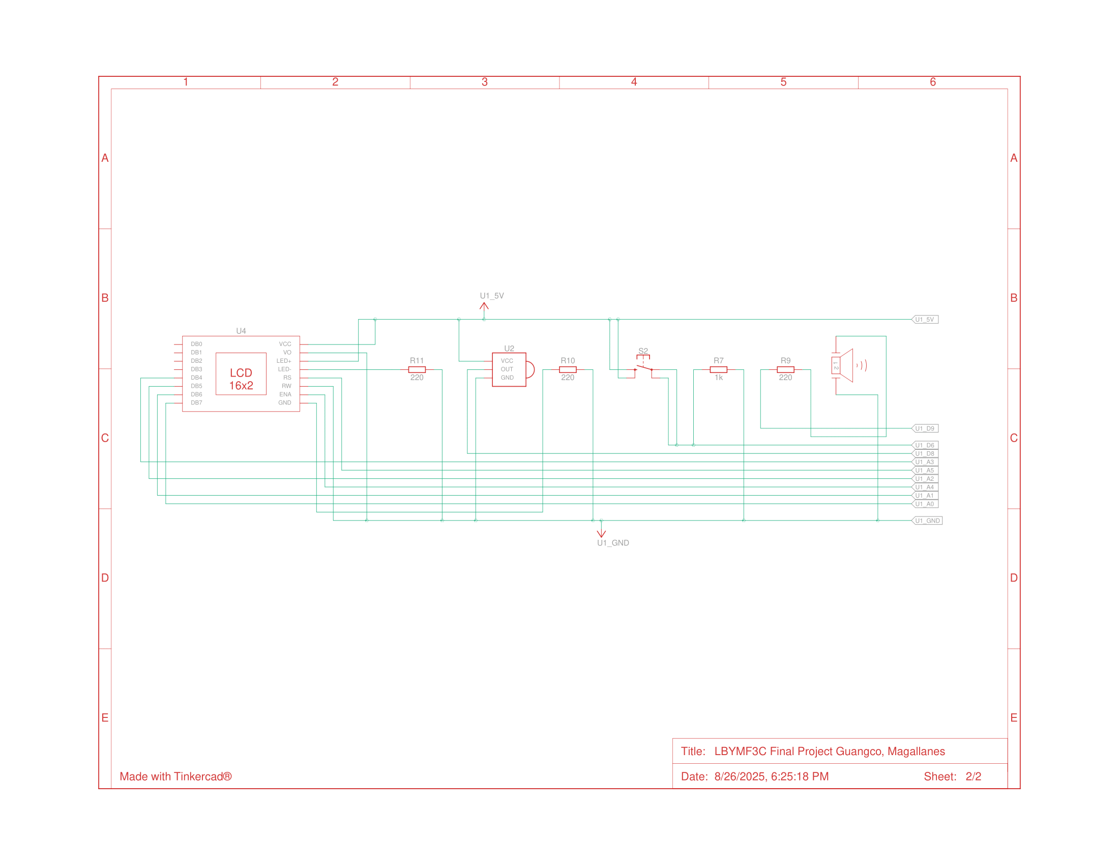
Below is the wiring diagram I was able to execute for the prototyping done in TinkerCAD!
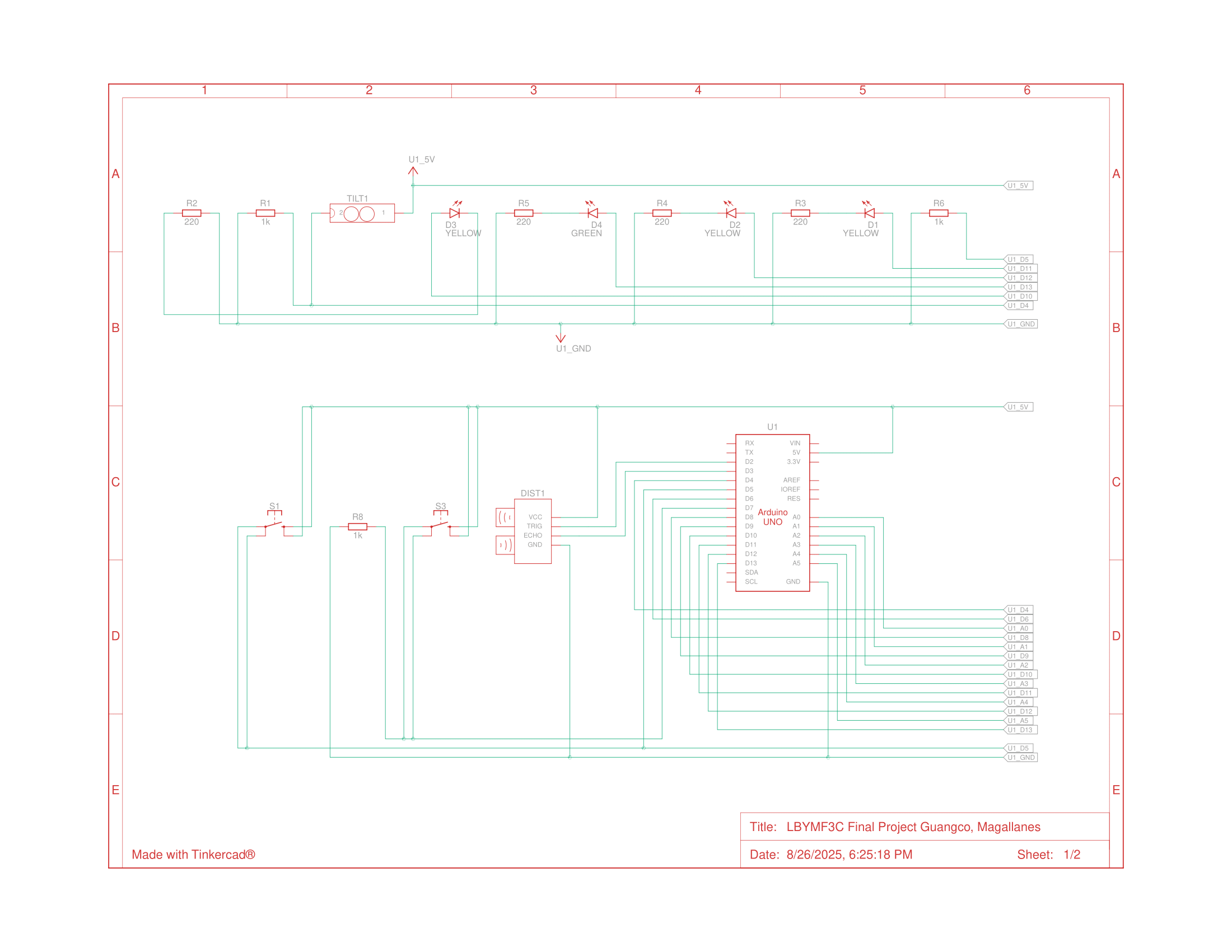
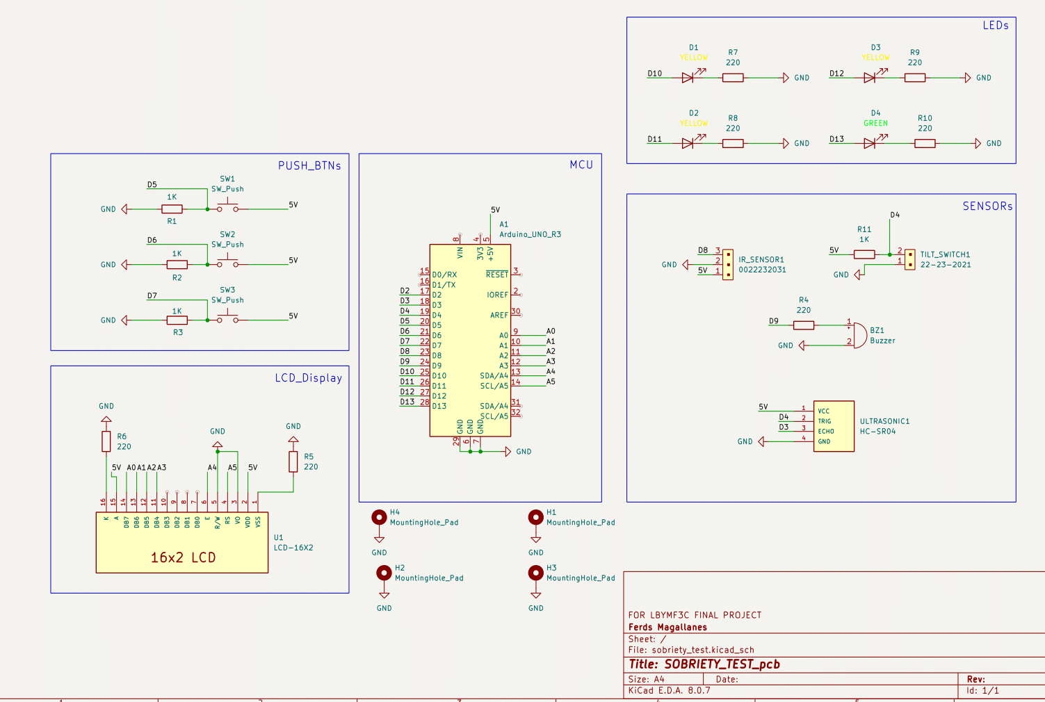
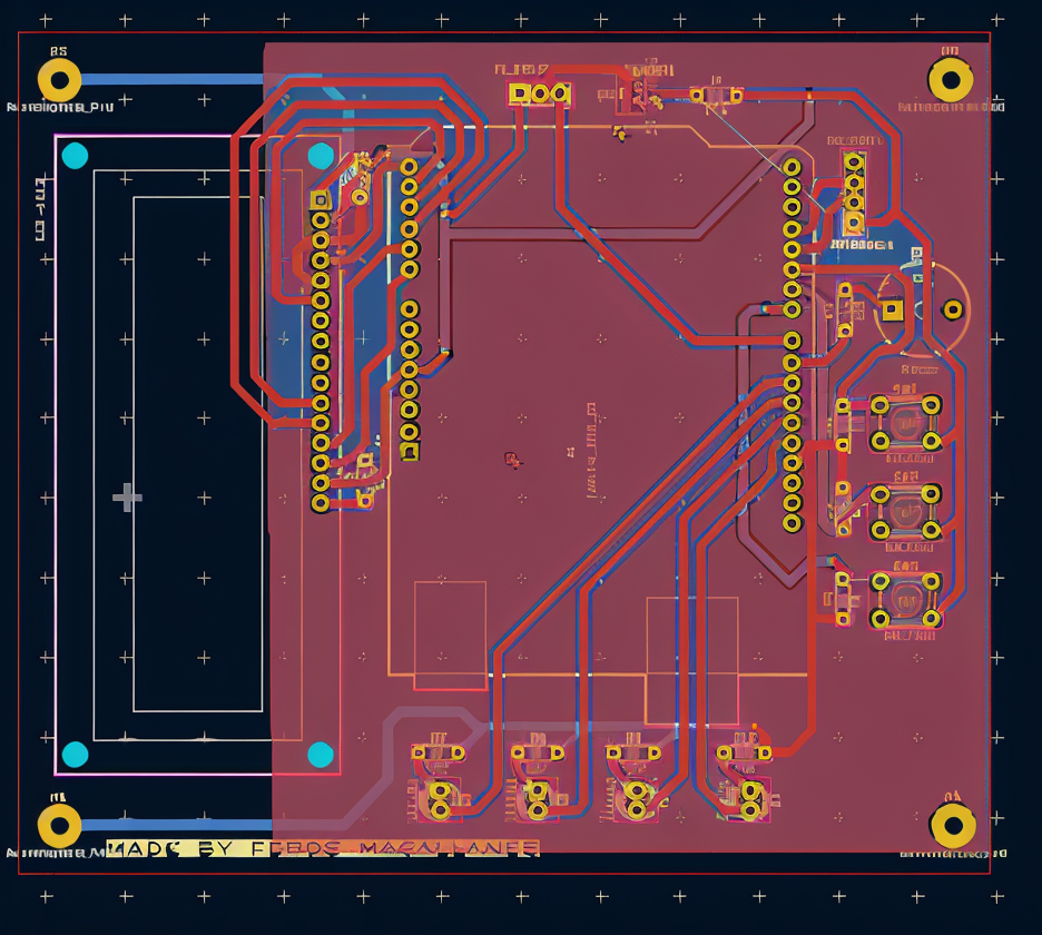
A better version of the schematic diagram and tracing done can be seen below where PCB designing under KiCAD software.
FINDINGS:
- Programming in C (Arduino IDE):
- Defined and managed multiple digital and analog I/O pins for sensors and actuators.
- Used built-in IRremote and LiquidCrystal libraries for input handling and display.
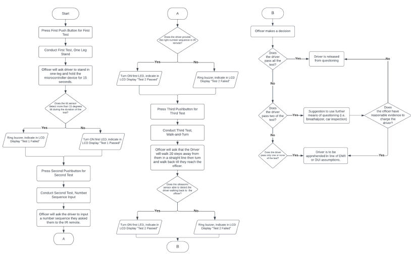
- Implemented functions for each test (balance, cognitive, walk-and-turn), showcasing modular programming in C.
- Applied if-else conditions, switch-case logic, and timers to control test flow and decision-making.
- Code can be seen in the final report given below!
- Sensors and Inputs:
- Tilt sensor → Balance test, detects >15° tilt.
- IR sensor + remote → Cognitive input test. The person conducting the test will ask the suspect to input a series of numbers / characters. (Initial presses to be: 12024597; can be modified based on available IR receiver keyboard)
- Ultrasonic sensor → Walk-and-turn distance check.
- Actuators and Outputs:
- LEDs → Visual cues for pass/fail.
- Buzzer → Alarm for failed tests.
- 16x2 LCD → Displays instructions, results, and test progress.
- Simulation & Testing:
- Conducted in TinkerCAD Circuits, with validation of input-output behavior.
- Debugging included syntax corrections, memory optimization, and handling IR remote logic through trial-and-error and documentation searches. simulation video can be seen below.
- A ready printed circuit board was made to prototype this efficiently for field testing. This can be seen below.
Based on the methods that I have shown above, I was able to achieve the following below. You may check our report too below :>
- Successfully executed three test modules controlled by push buttons in sequence.
- Proper sensor thresholds triggered actuator responses (LED, buzzer, LCD message).
- Maximized Arduino Uno I/O pin usage and memory allocation.
- Encountered but resolved issues with IR sensor programming and LCD I2C incompatibility.
- Delivered a video demonstration to showcase system functionality.
LEARNINGS:
Unfortunately, this project was a fully-online course and simulations of the physical product was all we can afford to provide but I was able to demonstrate here my familiarity with C programming fundamentals for microcontrollers especially pin configuration, variable declarations, modular coding, debugging. I’ve got to efficiently use libraries for peripheral control.
Aside from the above, I’ve got to learn the importance of simulation tools (TinkerCAD, Arduino IDE) in prototyping. Gained practical experience in sensor-actuator integration for real-world problem solving. Developed troubleshooting resilience when handling hardware-software mismatches. Realized the potential of microcontroller-based systems in public safety and intelligent automation.
WHERE I CAN IMPROVE UPON: Definitely, this project can be more practical with testing done in the field but was limited with what I have. Furthermore, I was heavily reliant to the tools to embed the code into the microcontroller. It will be better to try a different IDE to test this or a different implementation like bare-metals coding which I have yet to try based on completion of this project as well as different and smaller MCUs and components like Arduino nano that will lessen the board size and make it portable.
The project execution was longer than anticipated due to errors on footprints on the schematic where I had to find specific libraries for wanted components. Final tracing done was also unexpectedly tedious given that I had issues on the placement of the footprints and broken links to 3D models which I was able to resolve eventually. I think further use of local project library instead of placing all components in a common global one can ease the decision-making in the footprints and determine if libraries have the 3D models!
Further reflections and discussion about my experience in microprocessors/controllers can be seen here!.
PS. Shoutout to Adam for being a solid co-dev for this project!