CNC machining of a lathe vise
The machining and g-codes we have made to fab a lathe vise holder 🕹️
Overview
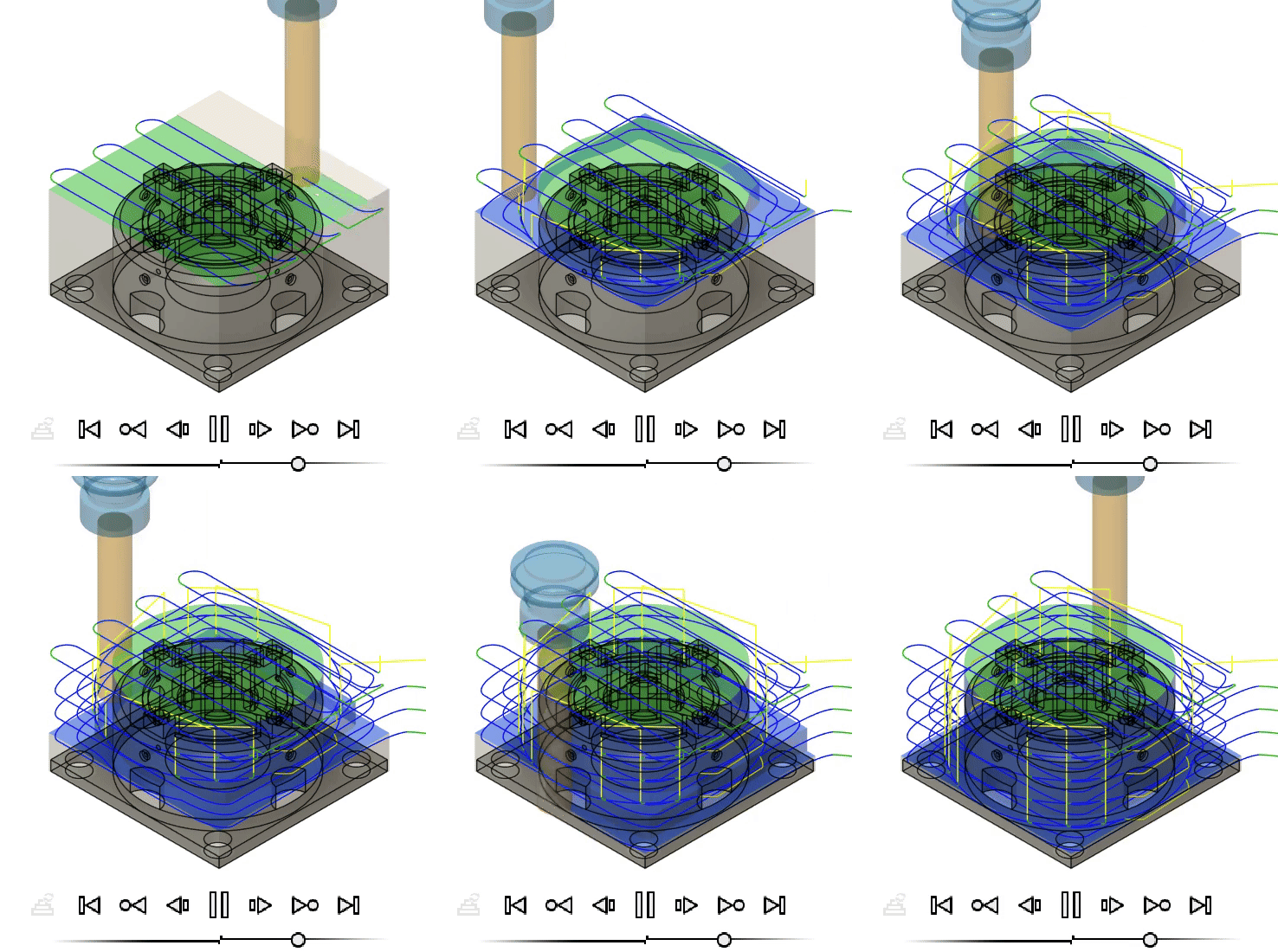
This project is the final demonstration that my group and I made for a laboratory course. This project involved simulating the complete CNC machining process for a part using Fusion 360 CAM. The task covered defining stock dimensions, setting the work coordinate system (WCS), selecting appropriate tools, and planning a full set of machining operations. The simulation aimed to optimize toolpaths, cycle times, and material removal strategies while ensuring dimensional accuracy.
The simulated job used a 172 mm × 172 mm × 93.5 mm stock where across 24 operations and 10 different tools (flat end mills, ball end mills, drills, spot drills), the part was manufactured virtually with an estimated total cycle time of 31 minutes and 43 seconds. The process integrated multiple machining strategies — including facing, adaptive clearing, contouring, drilling, and 3D toolpaths — with the goal of achieving both efficiency and precision.

Procedure
- CAM Setup
- Defined WCS (#0) aligned to the stock and part geometry.
- Specified stock dimensions, part offsets, and Z-height limits.
- Tool Selection
- Assigned 10 tools based on operation requirements, ranging from a 25 mm flat end mill (T3) for facing to a 4 mm drill (T16/T17) for small holes.
- Recorded tool data: diameter, length, spindle speed, feed rate, flute count, and holder type.
- Operation Planning
- Facing (Op 1) – Flattening stock surface for reference.
- Adaptive 2D & 3D Toolpaths – Roughing and clearing large material volumes with optimal stepdown/stepover.
- Contour Operations – Finishing external profiles and precision edges.
- Drilling Cycles – Creating holes with spot drills and standard drills, adhering to correct feed/speed.
- Slotting & Rim Machining – Using smaller diameter tools for internal slot and rim features.
- Simulation & Verification
- Ran full toolpath simulation to check for collisions, tool reach limitations, and excess material.
- Verified estimated cycle times, feed rates, and spindle speeds for each operation.
- Optimization
- Sequenced operations to minimize tool changes and travel distance.
- Adjusted stepdowns, stepover, and stock-to-leave values to balance material removal rate and surface finish.
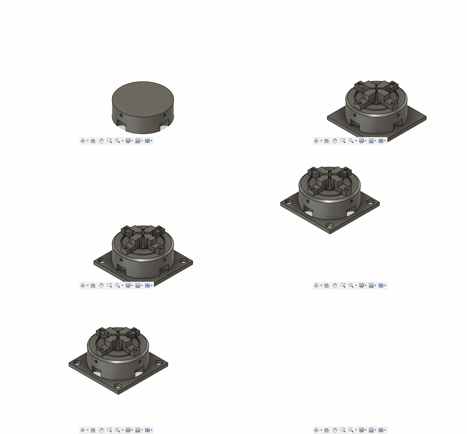
The final part can be seen in the figure below!

Learnings
We got the joy to actually see the part being machined in Fusion 360 CAM and apply G-Code. This was a great learning experience for me as I want to apply this in future projects and in work. Specifically, I was able to learn the following from this project:
- CAM Process Mastery – Gained experience in setting up complete CNC machining workflows in Fusion 360, from stock definition to final verification.
- Tool-Operation Matching – Learned how to select the correct tool type, size, and cutting parameters for specific geometry and features.
- Operation Sequencing – Understood how to arrange operations for efficiency, reducing unnecessary tool changes and rapid moves.
- Machining Strategies – Explored differences between adaptive clearing, contouring, facing, and drilling strategies, and how they affect cycle time and finish.
- Feed & Speed Optimization – Learned the trade-offs between high feed rates for roughing and lower feed rates for finishing accuracy.
- Simulation Benefits – Recognized the value of virtual simulation to identify potential collisions, inefficiencies, and overcuts before actual machining.
- Precision & Tolerance Awareness – Applied tolerances down to 0.01 mm for critical features, ensuring the virtual process meets manufacturing standards.
PS. You may check the adjacent blog post that I have made regarding supplementary exercises that I have done too here.
You may also check my works done for more other CAM activties where I actually was able to utilize a 5-axis CNC machine and laser cutting operations here.
PPS. Thanks to my co-implements for this project; Drix and Lance!