CMM Inspection Fixture for Gearbox Cover
A fixture precision tool for securing components during metrology measurements 🛠️
OVERVIEW:
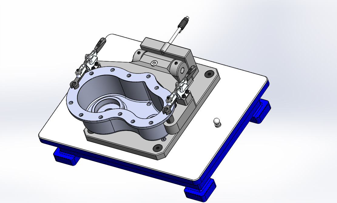
The motivation for this project is upon seeing mega-fixtures in parts assembly in Mitsuwa Chemicals from my field trip (blog can be seen here :>) Seeing the functionality of these fixtures for their parts function dojo where they assess particularly if the measurements of the parts manufactured is standard, I aim to also modify and determine a test fixture. Thankfully, coinciding with my studies, I was able to obtain a coordinate measurement machine (CMM) inspection fixture model design for gearbox cover use where the idea is to immediately determine if the cover is defective or not based on stamping the gearbox on a predefined positioning locators via the balls beside the clamp.
This all in all provides a GD&T analysis of the gearbox cover and its parts with minimal clamping surface which is ideal for a high throughput checking of the acceptablity of the product within an assembly line. Further utilization of this is via a dial gauge or a precise CMM that checks if the measurements are within nominal values or within expected deviation.
The fixture adheres to tool design,restricted planes of movement, support principle, and locating principle. Findings outline a more thorough explanation of the design made.

FINDINGS:
1. Tool design
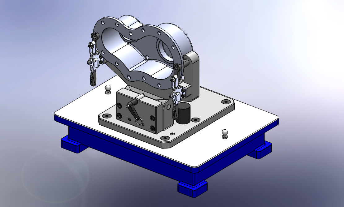
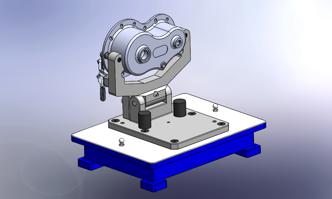
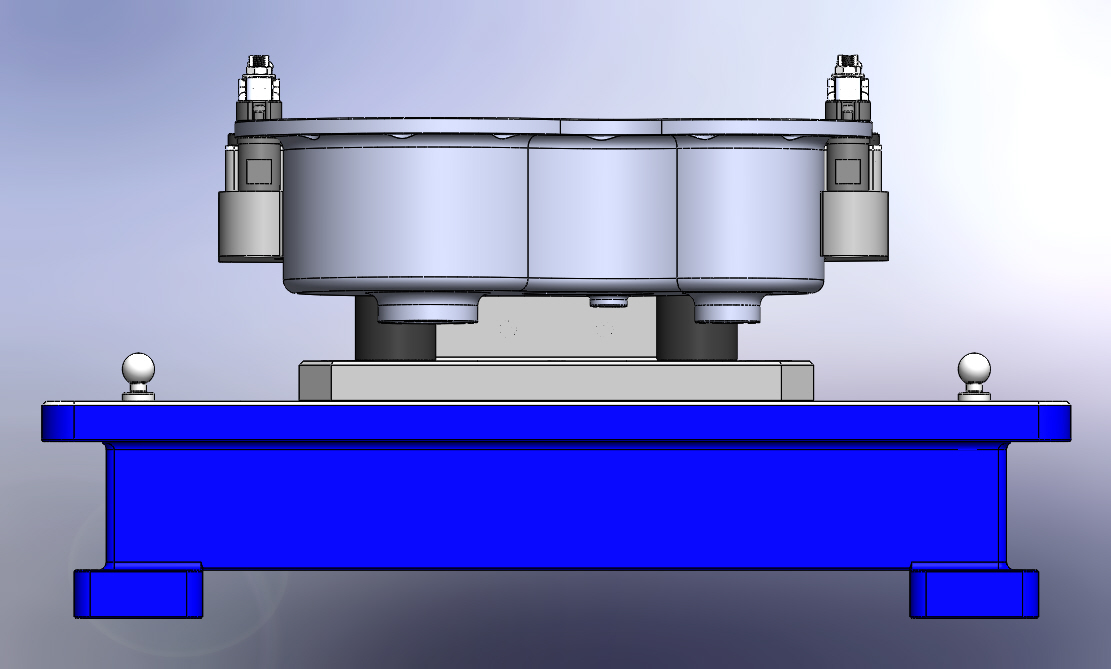
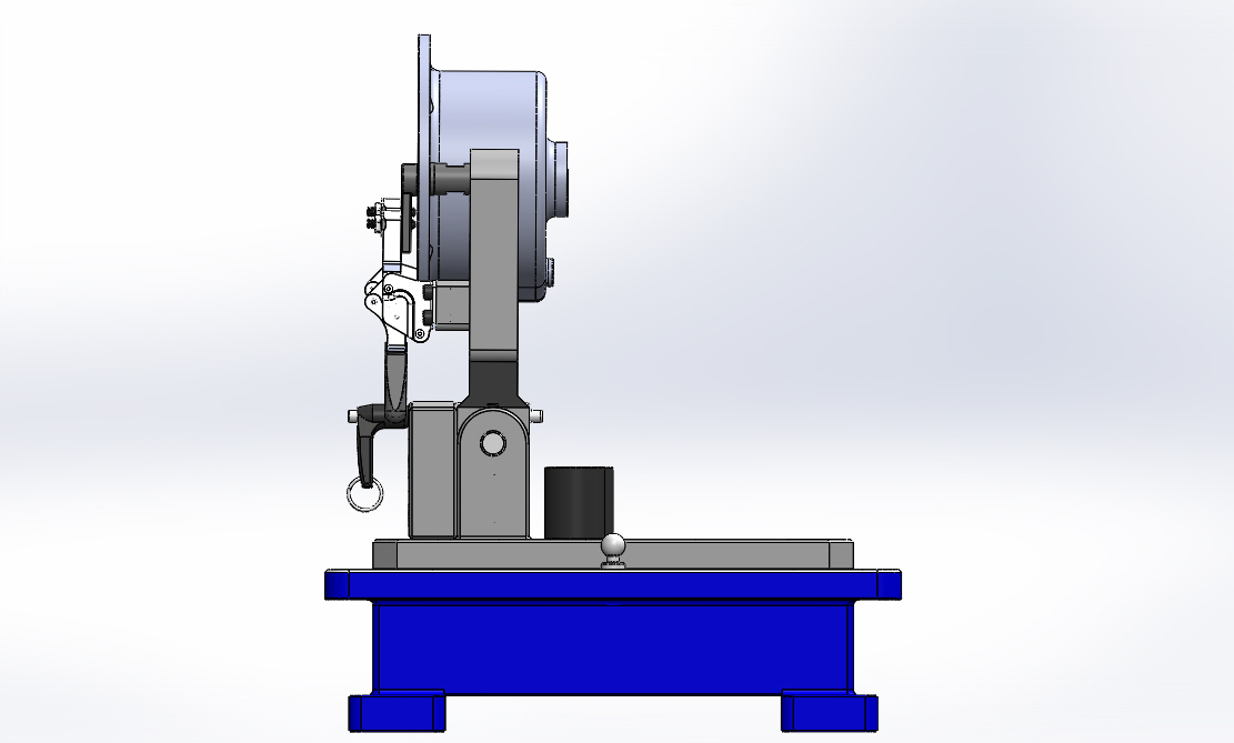
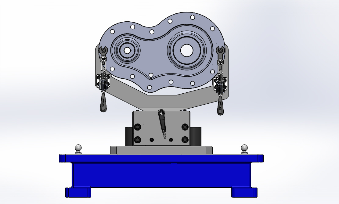
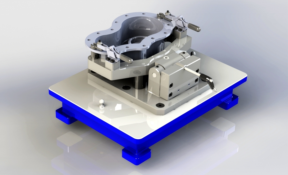
- The fixture body is a built-up tool (steel or epoxy-resin alternative) composed of base, brackets, swing arms, clamp assemblies and locators — a modular approach that makes part loading and maintenance easier.
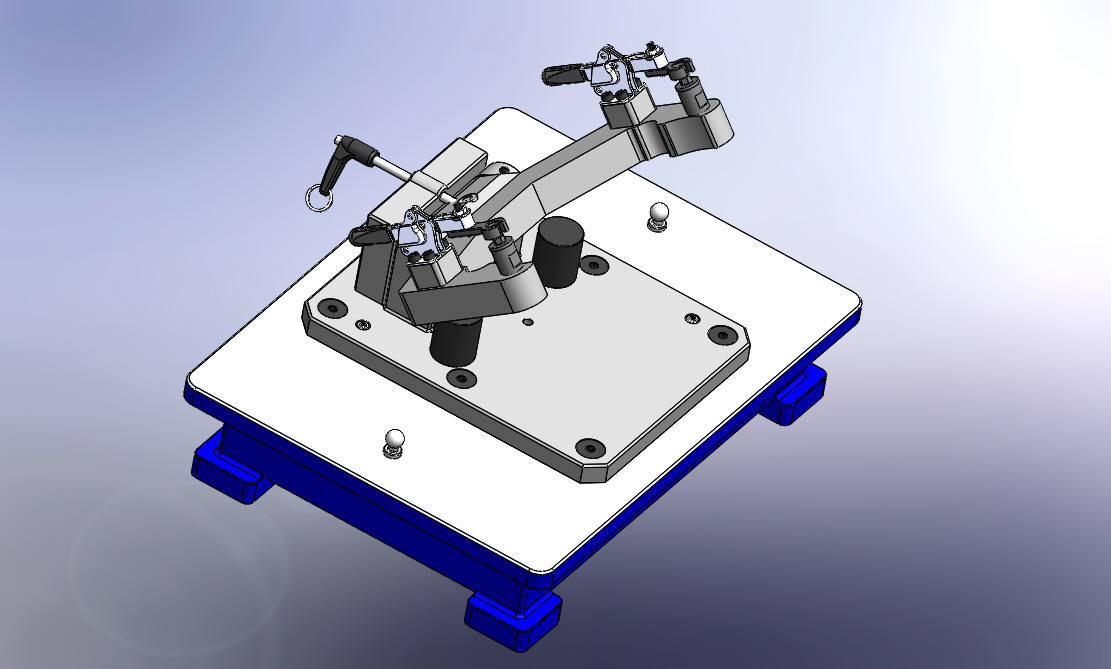
- Toggle clamps provide quick, reliable clamping while minimizing part distortion; clamp locations were chosen to avoid measurement datums and probe paths.
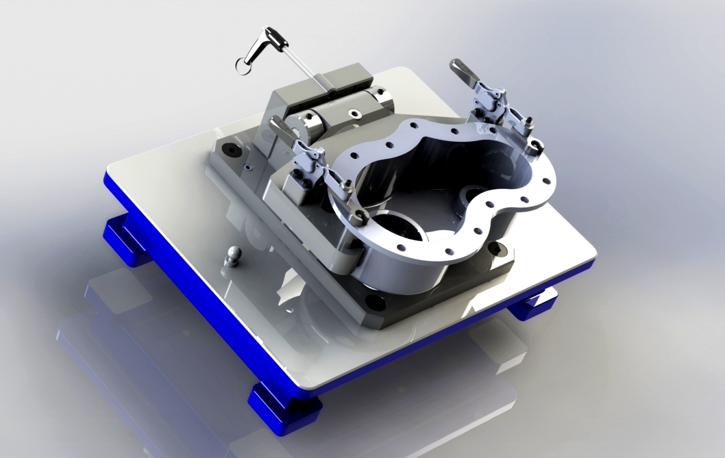
- Locating balls (two primary locators + redundant locator) ensure consistent seating and orientation of the gearbox cover relative to the CMM coordinate system.
2. Restricted planes of movement
- The fixture follows the 3-2-1 locating principle, effectively restricting the workpiece’s six degrees of freedom (DOF):
- 3 points on a primary plane to prevent translation along Z and rotation about X/Y.
- 2 points on a secondary plane to prevent rotation about one axis and translation along one axis.
- 1 point on a tertiary plane to prevent the final remaining translation.
- Simulation shows the part is constrained without over-constraint, allowing repeatable placement while avoiding induced stresses that could distort measurement.
3. Support principle
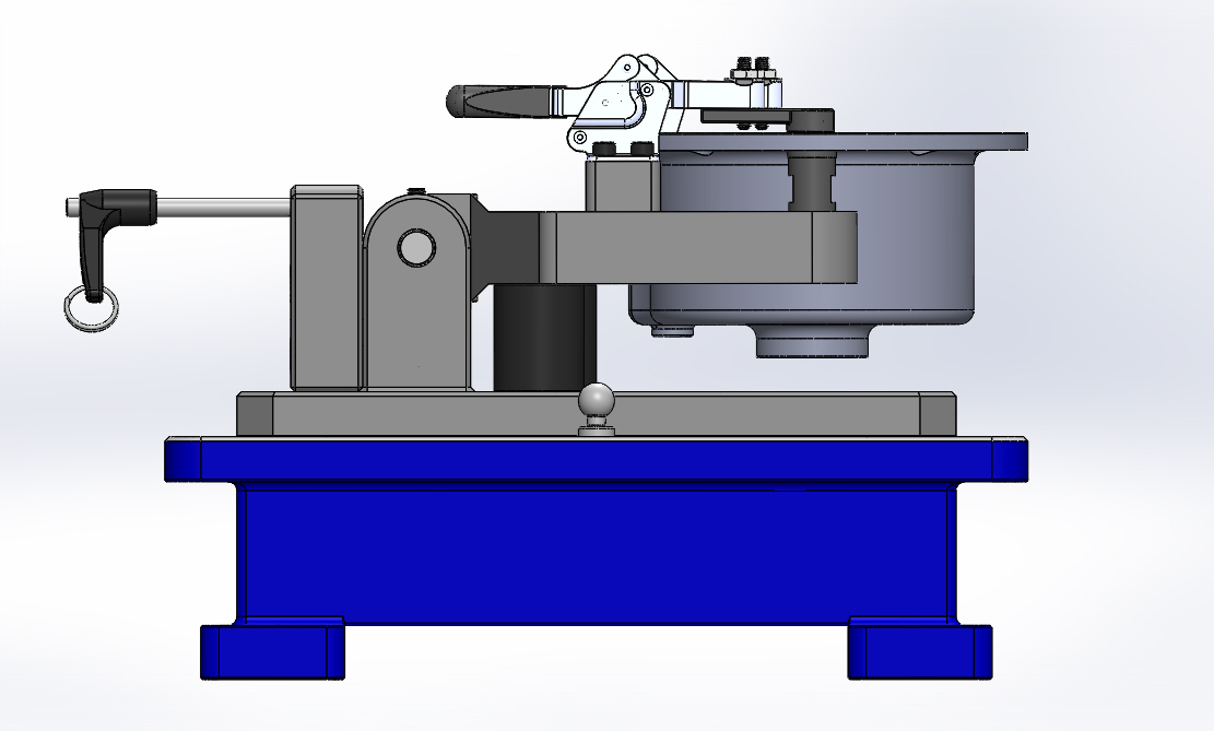
- Support features (bushings, brackets, support pads) were placed so the workpiece rests on designed support points rather than clamps alone — this keeps the part stable during probing and reduces clamp-induced deflection.
- Using distributed support (not single point load) reduces local deformation and improves measurement repeatability.
4. Locating principle (kinematic & datum definition)
- The fixture creates explicit datums: primary datum for orientation, secondary for rotation control, tertiary for translation — matching common GD&T practice and enabling direct mapping to the CAD model and CMM program.
- A redundant locator was included as a backup to ensure part orientation if a primary locator is worn or slightly damaged, improving robustness for production use.
LEARNINGS:
With this, I was able to synthesize a course regarding jigs and fixture design. To be specific I was able to:
- Design and simulate a CMM checking fixture (fixture body, locators, clamps, brackets, bushings) for a gearbox case cover.
- Ensured the part can be placed repeatably and measured by a CMM probe (probe access, probe clearance, and probe trajectories considered).
The specific learnings from this project are:
Tool design lessons
- Modularity matters: Designing detachable brackets and interchangeable locators speeds up fixture rework and adaptation to similar parts.
- Material tradeoffs: Steel gives stiffness and thermal stability; epoxy resin can reduce cost and weight but needs evaluation for thermal expansion and wear at locator surfaces. Choose based on expected inspection volume and environment.
On constraining motion (3-2-1)
- The 3-2-1 rule is a simple, reliable way to eliminate the 6 DOF while preventing over-constraint. Over-constraining (too many contact points) can introduce unpredictable stresses and measurement errors — kinematic locating (point, line, plane) is preferable.
On support vs clamp
- Support provides a stable reference; clamps secure the part without introducing bending moments on datums. Always design supports at load-bearing locations indicated by the part geometry — not at fragile features.
On measurement repeatability & probe access
- Design for probe accessibility (probe tip clearance & collision avoidance) while placing locators and clamps outside measurement areas. Simulation validated probe paths in the fixture model.
- Repeatability is improved when contact surfaces are hard, wear-resistant, and small in area (e.g., hardened steel balls, dowel locators) so the exact seat point does not change with successive parts.
On inspection workflow
- Fixture design should align with CMM program datums and the CAD nominal features so measured values map directly to GD&T checks — this simplifies programming and reduces interpretation error during inspection.
You may check my report for this project below~!
REFLECTIONS: Further reflections and learnings that I have made regarding jigs and fixtures can be seen at this blog post here. I say that this is a fixture because the workpiece is being hold via clamps and there is no cutting tool involve. But this can be also jig if you will consider that the measurement tool can be guided properly in what reference point should be checked. Furthermore, a CMM that electronically captures the measurements via lasers will provide a more accurate values. This fixture holds the workpiece and ensures that the lasers examining the piece is within expected GD&T.
HOW THIS PROJECT CAN BE FURTHER IMPROVED: This project is just the CAD version therefore the actual dimensioning and validation of the tool design rest in machining the model which is ready if ever. An issue that is common in inspection jigs and fixtures is the workpiece not being secured in place via the clamps. This is attributed mainly by the vice and the contact points. Further exploration on a better contact point like rolling ball or ratchet mechanism is highly recommended for future works!!
PS. Huge thanks to Adam for being a solid groupmate for this project.