Determination of reactions made for a 2-part flange assembly connection
Case of applying remote force (moment!) to simulate structural loading offset
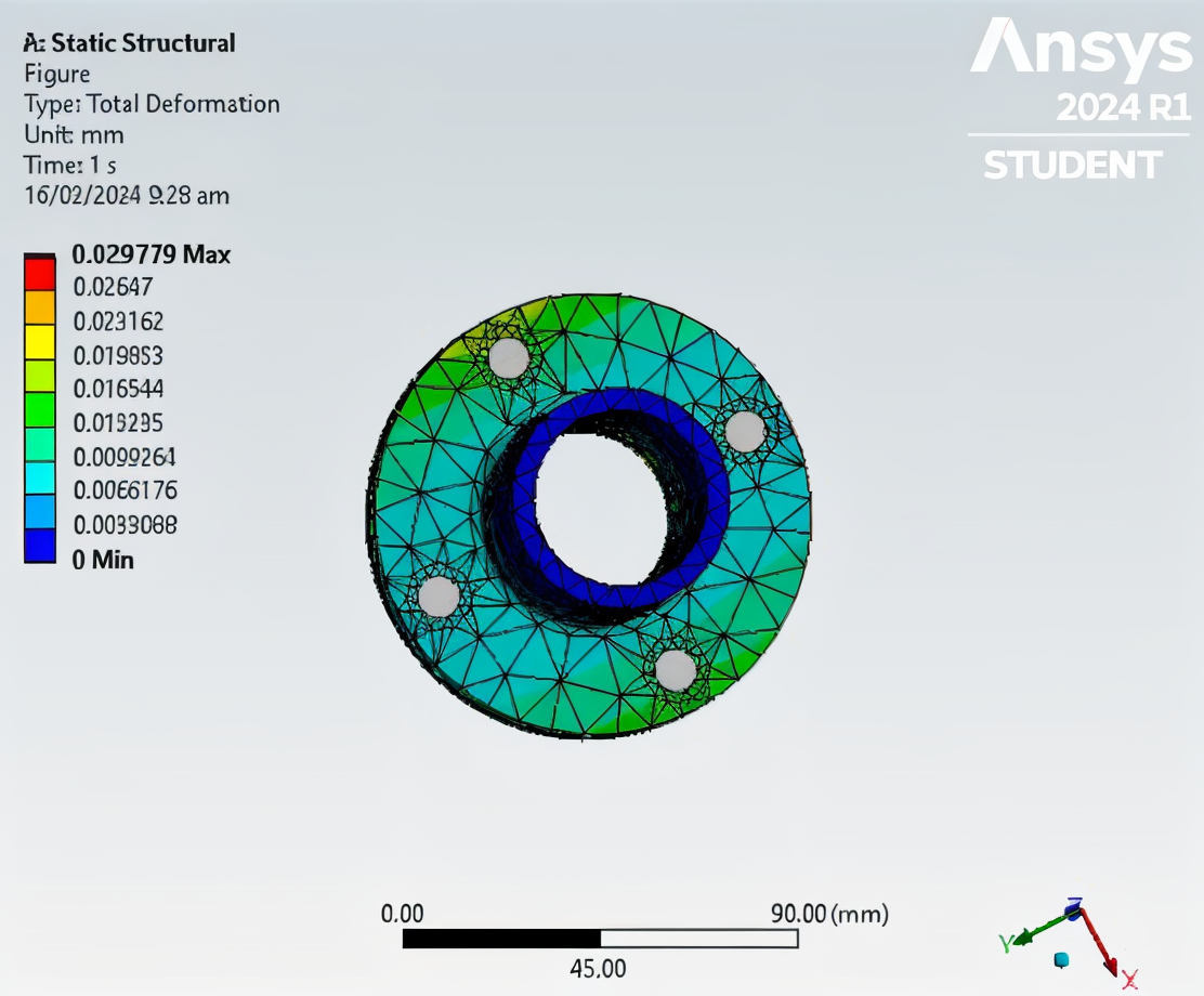
About the Thumbnail: This is the total deformation felt per mesh element in millimeters visualized in the workpiece! Further explanation can be seen in the discussion below
Overview
This finite element analysis (FEA) project explored the beam connection feature within ANSYS Mechanical to model fasteners in a flange assembly system. The analysis simulated a realistic remote axial load offset from the flange axis to induce both tensile and bending (moment) effects on the assembly.
The goal was to visualize how the flange–fastener system distributes load under offset structural forces and to evaluate the Von Mises stress, reaction forces, and deformation behavior. This experiment reinforced the concept of load transfer through finite element connectors and its impact on mechanical joint integrity.
Note: I can provide our CAD and project file upon request! Kindly comment in this post
Methodology
I have tabulated the simulation setup for replication. The idea basically is to apply beam connectors within each fastener, allowing for axial, shear, and bending load transmission. This is not explicitly provided in the CAD file (if you notice, there are no fasteners in the mount flange!) therefore we need to place this into our setup that will counteract the applied load which is applied vertically and with an offset from the center. The amazing thing that I did here was that the force applied was not directly in the center of gravity of the workpiece therefore there will be a moment induced upon calculation.
| Parameter | Value / Description |
|---|---|
| Software Used | ANSYS Mechanical |
| Analysis Type | Static Structural |
| Material | Structural Steel (E = 200 GPa, ν = 0.3, ρ = 7850 kg/m³) |
| Beam Connection Type | Line body fasteners between plate holes |
| Applied Remote Force | 1000 N (axial) along Z-axis |
| Offset Distance | 100 mm from the central flange axis |
| Boundary Condition | Fixed support on rear flange face |
| Solver Type | Direct Sparse Solver |
| Element Type | Beam188 (for connectors), Solid186 (for flange bodies) |
Findings
1. Stress Distribution
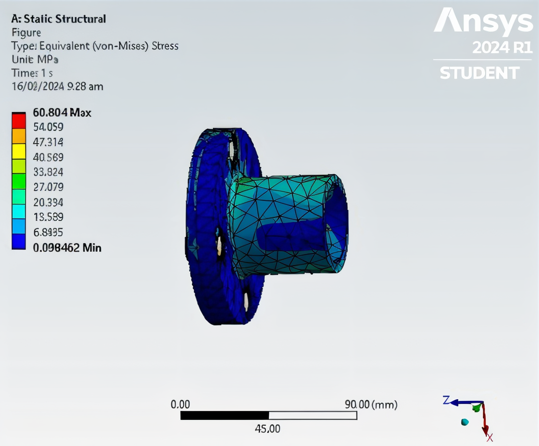
- The Von Mises stress distribution across the flanges revealed stress peaks concentrated around the beam connection regions nearest the load application.
- Maximum Von Mises stress observed: 60.8 MPa (located near the upper fastener area).
- The opposite flange exhibited lower stress gradients, confirming effective load transfer through the fasteners.
- These values are below the yield strength of structural steel (≈250 MPa), ensuring elastic behavior.
If you know the basics of mechanics of deformable bodies, von mises stress is the equivalent force felt in given area for maximum distortion where the material will yield. Amazingly, the flange design holds well under the stress as mentioned with lower stress gradients that you may check in the figure below.

2. Deformation Profile
- Maximum total deformation occurred at the outer flange edge near the load offset point.
- Recorded maximum displacement: 0.03 mm at the tip of the loaded flange face.
- Minimal displacement was observed on the fixed flange, as expected.

3. Reaction Forces
- The fixed support experienced a reaction force equal in magnitude (≈3000 N) and opposite in direction to the applied remote load.
- Due to the 25 mm offset, the force generated a bending moment ( M = F \times d = 3000 \, \text{N} \times 0.025 \, \text{m} = 75 \, \text{N·m} ).
- This induced localized bending stresses that propagated through the bolt connectors, slightly increasing the stress near the upper fasteners.
You may check the report that I have for this study below.
How this can be further improved: One of the easiest sanity checks that one can do when analyzing for this type of FEA study is to determine if it proceeds as expected on the right-hand rule if the part turn clockwise or counter-clockwise given force displacement for direction of moment. Of course, this is the most basic calculation that we, as engineers, do in terms of moment applied in deformable bodies. In this case, the deformation moved upward away from given load directed at Z-axis, our axis of rotation. With this, I’m confident that this study is as intended.
Given that the deformation is less than 0.03 mm, I doubt that it will be visible in study but the made beam probe has the most stress felt which is expected since these are where the fasteners are placed.
If you are interested to more blog readings of my work about FEA, you may check it here