Modal analysis for a machine frame
How a workpiece work under natural vibrations
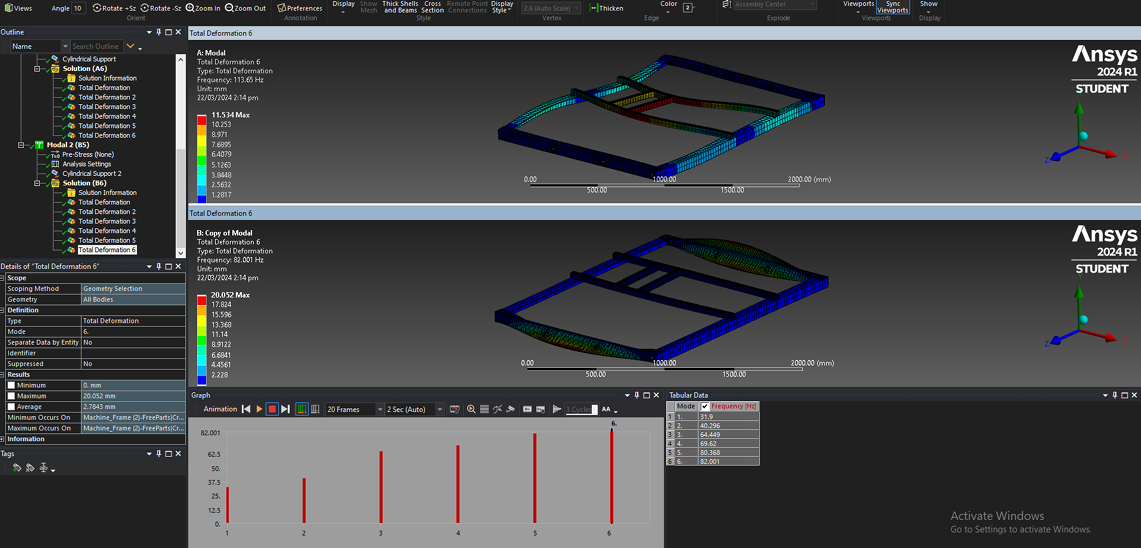
About the Thumbnail: This is the total deformation felt per mesh element in millimeters visualized for the workpiece where in a frequency of 113.06 Hz is felt. This is constrined for the 8 holes on the sides! Further explanation can be seen in the discussion below
Overview
This study presents a modal analysis conducted on a machine frame to determine its natural frequencies and mode shapes under two mounting configurations — four-hole and eight-hole supports. The objective was to evaluate which configuration provides better vibration resistance and structural stability.
One of the things that makes this type of study important is if the product can withstand resonance frequencies and mode shapes where the structure may experience excessive vibration. Using ANSYS Mechanical, this simulation validates the dynamic response of the machine frame and ensures its mechanical integrity under operating conditions.
Note: I can provide our CAD and project file upon request! Kindly comment in this post
Methodology
The geometry of the machine frame assembly was imported as a STEP file into ANSYS Workbench. The frame was composed of eight structural bodies—rails, crossbars, supports, and mountbars—each assigned Structural Steel material with:
| Property | Value |
|---|---|
| Density (ρ) | 7.85×10⁻⁶ kg/mm³ |
| Young’s Modulus (E) | 200,000 MPa |
| Poisson’s Ratio (ν) | 0.3 |
| Yield Strength | 250 MPa |
A bonded contact setup was automatically generated among all bodies to ensure connectivity
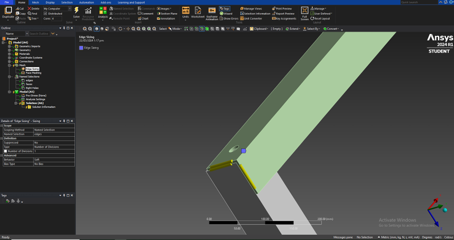
Meshing and Named Selections A mechanical mesh was generated using an element size of 30 mm with adaptive sizing and medium smoothing. Named selections were applied to define:
- Edges and faces of the frame for vibration recognition.
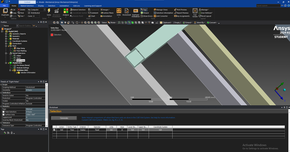
- Mounting holes (20 mm diameter) grouped as either:
-
Eight Holes(full support configuration) -
Four Holes(reduced support configuration)
-
These selections defined the cylindrical support constraints, which were used to simulate mounting conditions. This boundary condition and modal setup makes it viable for the testing what is the best configuration given other constraints like that of cost or space for doing mounting holes.
Boundary Conditions and Modal Setup
Two separate modal environments were analyzed:
- Modal (A5): 8-hole mounting configuration
- Cylindrical Support: Radial and axial fixed; tangential free.
- Modal (B5): 4-hole mounting configuration
- Cylindrical Support: Radial, axial, and tangential fixed.


The analysis aimed to extract six natural modes for each configuration, covering a frequency range up to ~120 Hz. No pre-stress conditions were applied (pure modal analysis).
| Setting | Value / Description |
|---|---|
| Solver Type | Mechanical APDL |
| Max Modes to Find | 6 |
| Damping | None (undamped) |
| Temperature | 22°C |
| Result Outputs | Mode frequencies, total deformation |
Findings and Results
Natural Frequencies
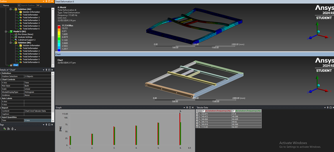
The simulation extracted the first six natural frequencies for both mounting configurations:
| Mode | 8-Hole Support [Hz] | 4-Hole Support [Hz] |
|---|---|---|
| 1 | 32.071 | 31.900 |
| 2 | 40.472 | 40.296 |
| 3 | 66.664 | 64.449 |
| 4 | 69.773 | 69.620 |
| 5 | 80.818 | 80.368 |
| 6 | 113.650 | 82.001 |
The 8-hole configuration consistently exhibited higher natural frequencies, indicating greater stiffness and lower susceptibility to resonance within the same frequency domain.
Deformation Behavior
For each mode, the maximum total deformation was measured. The highest deformation occurred at the support beams and rail regions near the free boundaries:
| Mode | 8-Hole Max Deformation (mm) | 4-Hole Max Deformation (mm) |
|---|---|---|
| 1 | 9.21 | 9.19 |
| 2 | 9.17 | 9.11 |
| 3 | 7.83 | 7.61 |
| 4 | 10.90 | 10.94 |
| 5 | 14.42 | 13.92 |
| 6 | 11.53 | 20.05 |
The sixth mode displayed the most significant contrast: the 4-hole mount reached 20.05 mm deformation, while the 8-hole setup limited this to 11.53 mm—a 9 mm reduction in dynamic displacement. This quantitative difference validates that the 8-hole configuration dissipates vibration energy more effectively.
Findings
The modal data explicitly validate the mechanical performance of the machine frame.
Key insights include:
- Higher natural frequencies in the 8-hole setup confirm increased stiffness and improved resistance to resonance.
- Lower deformation amplitudes indicate that additional mounting points effectively dampen vibrational energy, distributing dynamic loads across more supports.
- The mode shapes revealed that deformation concentrated near unsupported regions, emphasizing the importance of symmetric support design.
- From a design perspective, increasing the number of supports or adding parallel dampeners would further minimize the vibration amplitude, as noted in vibration control theory.


In real machine systems, avoiding resonance at the operating frequency range (typically below 100 Hz for mid-sized machinery) ensures longevity, noise reduction, and alignment stability. Hence, the 8-hole configuration provides a validated, more reliable frame design.
You may check the report that I have made below!
How this can be further improved: It’s easy to get lost in the results. Proper analysis of the values provided and understanding of why we are making this study is essential talaga. Based on the given, having fluctuations beyond 100 hz can comprise immediately the integrity of the system, where in deformations of up to 11.53 mm is felt on a 113.65 hz range for 8-hole support. As expected 4-hole support has a greater of 20.05 mm. Contrary though to common logic, 4-hole support perfomed on par with the 8-hole support for the other frequency test modes.
What does this mean then? you can pick the 4-hole support any given case since it provides the same performance as the 8-hole configuration for natural occuring frequencys before noticeable deformation is seen. For comparison, 20 hertz is the given frequency range for seismic waves. So having 110 hz is unreasonable for a machine frame especially if the frequency is natuarlly occuring. Concern more if this frame will be subjected to moving parts, then oscillations from this movement will then reach frequencies within 110 hz range.
TLDR, 4-hole support chosen for static and cyclic loading given low loading rate; 8-hole support or dampners are required if ever the moving loading exceeds 50-100 hz to minimie known deformation to machine structure!
If you are interested to more blog readings of my work about FEA, you may check it here